In need of 2x6L6GC power amp expertise

General discussion area for tube amps.

Moderators: pompeiisneaks, Colossal

Bergheim
Posts: 90
Joined: Tue Jan 29, 2019 7:45 pm
Location: Norway

In need of 2x6L6GC power amp expertise

Post by Bergheim »

Hi all! Calling out for a little expertise.

A while ago I got my hands on a Peavey Deuce VT (solid state preamp, 4x6L6GC fixed bias power amp) and decided to do a complete rebuild.
At this point the amp is up and running with parallel 12AX7 input stage -> james tonestack -> EF86 -> 12AT7 LTP phase inverter and 2x6L6GC self-biased power stage.
I'm having problems driving the power tubes to full blast, and I have to really abuse the preamp to get the 6L6GC's to clip even slightly. I suspect it's the plate/screen voltage or output impedance that limits the performance and I need to get this confirmed. I've tried a lot of tweaks in the LTP to ensure it doesn't clip prematurely and thus limit signal swing, and I actually wired a 50k LIN pot in place of the tail resistor and a 5k LIN pot in place of the cathode resistor. Surprisingly there were no audible difference between 50k tail and ~10k tail, although I settled for 12k as it balances the tride halves very well and it gives a lot of headroom just taking up 10-15% of the available B+ voltage. Long story short I think the LTP has enough potential to drive the power tubes well beyond full power.

The output transformer has two output taps with impedance ratios of 445:1 and 230:1.
For the 445 tap the possible impedances are 1780, 3560 and 7120 plate-to-plate with 4, 8 and 16 ohms load respectively.
For the 230 tap the possible impedances are 920, 1840 and 3680 plate-to-plate with 4, 8 and 16 ohms load respectively.
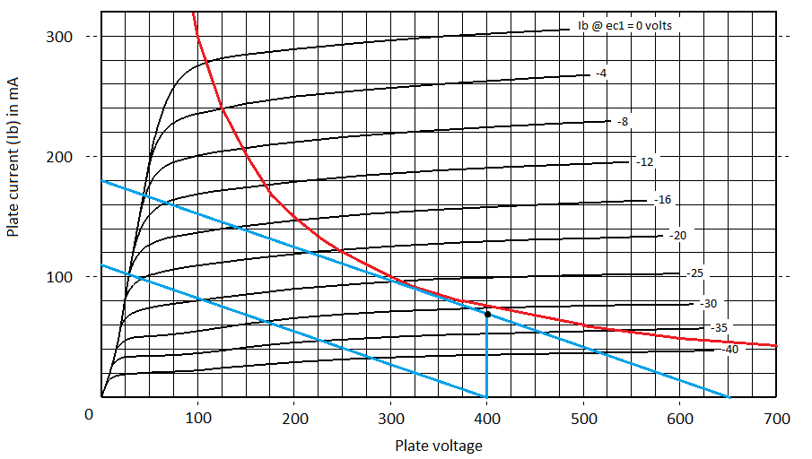
At this moment I'm running 16 ohms load into the 445 tap for 7120 ohms (3680 ohms per tube) which I believe is the most correct impedance for this build (see load line below). With around 400V on the plates it seems I'll have to bias really cold to avoid the load line exceeding plate dissipation, although 400V plate voltage seems quite normal for these tubes.

Running four 6L6GC's would naturally allow a few more possibilities impedance-wise, but I'm not sure if the heater windings can withstand the extra current to the preamp tubes. I've asked Peavey tech support but they didn't have the specs anymore and I don't wanna risk frying the windings.. TAD makes an aftermarket tranny for the Deuce VT which has a 3.8 amperes heater rating. That leaves 0.2 amperes for preamp tubes.. Is it safe to assume that Peavey overbuilt the tranny enough to safely run the preamp tubes in addition to the four 6L6GC's?

Anyway, my observations/ideas so far:
- Lower the screen voltage to get the g1 0V knee just above the load line. Increased sensitivity makes the tubes easier to drive, and it'll match the Zout nicely, right?
- Lower the plate voltage to allow lower output impedance which would recuire a pretty big zener/resistor.
- Fixed bias. I read somwhere that cathode bias should not be used with very high plate voltages because it's hard to find OT's with correct impedances, but I can't see the logic in this (so far). Anyone know if this is true and care to explain why?

Initially I thought I had a fairly good grip on how to set up a power stage like this but I think I might need some input.

Image
Image
Last edited by Bergheim on Sun Nov 10, 2019 10:27 pm, edited 1 time in total.
User avatar
Tony Bones
Posts: 228
Joined: Thu Oct 30, 2014 8:24 pm

Re: In need of 2x6L6GC power amp expertise

Post by Tony Bones »

I don't know if I'll address all of your questions (there seems to be a lot.) But I'll make a few comments:

1. 3.6k total load impedance is probably about right for 2x6L6.
2. Using cathode bias when running PP class AB is a challenge because the bias ends up changing with signal level. As you drive the tubes harder they draw more current and bias themselves colder.
3. You really need to bypass the cathode bias resistors. It'll need to be a large cap like 100uf / 100V. Without bypassing, the local NFB makes it even harder to drive the tube to clipping.
4. I don't think the EF86 is setup to provide as much output voltage swing as it could be. Take a look at the recommended operating conditions on pg2 of the Philips datasheet. It suggests Ra = 100k, Rg2 = 390k, Rk = 1k, should provide 64V peak output, which is about what you want.
5. The 220k/220k voltage divider going into the the PI isn't helping.

#5 and #5 might not be issue at all, but #3 above means that even if the tubes are nominally biased at 40V (for example) it might take 80V peak to drive them to clip. #2 compounds the problem.

Cathode bias can work with output tubes even in Class AB, but it makes it harder to drive the tubes to clipping, if that's a goal. You might try fixed bias.

As for the capacity of the power transformer, I have no idea what Peavey made, but changing from 4 two 2 output tubes buys you more than enough current capacity for the preamp tubes.
Bergheim
Posts: 90
Joined: Tue Jan 29, 2019 7:45 pm
Location: Norway

Re: In need of 2x6L6GC power amp expertise

Post by Bergheim »

1. Yep, that's why I'm thinking 7k (plate to plate) as my seemingly only option just can't be right.
3. Schematic error. They're bypassed with a 100uF 400V electrolytic each.
4. The EF86 will be tweaked indeed. I used Merlin's tutorial to set it up, and it actually beats the snot out of the LTP. I wired a 1Meg volume pot between the EF86 and the LTP in place of the divider to limit signal into the LTP mainly to control and "monitor" distortion of the two stages. But yeah I'm gonna work on the EF86, primarily to get lower headeroom as I want pentode distortion without having to dump 99% signal before the LTP.
Bergheim
Posts: 90
Joined: Tue Jan 29, 2019 7:45 pm
Location: Norway

Re: In need of 2x6L6GC power amp expertise

Post by Bergheim »

I've done some more research on load lines and dissipation limits for class AB1 in which this amp is supposed to operate.
It seems that while using a 7k p-p load won't exceed any limits or ratings of any sort, it holds back the power potential quite a lot compared to similar topologies. It also seems 400-450V plate voltage and 3.8-4.2k p-p load are common values used throughout the age of guitar amps.
Perhaps I've been too obsessed with Merlin's statement in his push-pull tutorial (http://www.valvewizard.co.uk/pp.html) that the class A load line should never cross the dissipation curve whereas the class B load line may cross this curve a bit, as his design example seems to be one of very few designs that don't cross the dissipation curve at all.
The more I've searched, the more it seems that the dissipation curve mostly relates to the quiescent current dissipation. Somewhere I came across a statement saying that anything up to twice the dissipation limit is okay for the class B load line, as the tube only operates in this condition for a small part of it's cycle. Additionally, many classic designs seem to ignore if or how much the class A line crosses the limit as long as the quiescent point is ok.

Anyway, I've decided to try 3.7k p-p for more potential power (cathode biased for now for the sake of simplicity). I've plotted the class A (3700/2=1850ohms) and B (3700/4=925ohms) load lines for 410V plates (~30V cathode bias subtracted). The "slided" class A line shows quiescent point at 70% operation. Screen voltage is currently 350V but it seems I need to increase it to ~430V for the line to hit the knee. For that matter, how to you think it will perform with the load line hitting way above the knee at 350V? Just lower voltage swing, all thing else being equal?

Do the loadlines seem reasonable and doable? Should I go fixed bias? As the amp was initially fixed bias I do have a 50V winding available. Reading through the forums it seems cathode bias doesn't work very well with anything other than very hot AB which will possibly fry the tubes.

I've also updated the schematic with some changes in the phase inverter

Image

Image
Last edited by Bergheim on Sun Nov 10, 2019 10:36 pm, edited 1 time in total.
User avatar
Reeltarded
Posts: 10189
Joined: Sat Feb 14, 2009 4:38 am
Location: GA USA

Re: In need of 2x6L6GC power amp expertise

Post by Reeltarded »

If I were doing this for a first time out, I would do it like this:

Stage 1- EF86 - V1b as a CF -TS -12ax7 LTP -Common 6l6 output biased however.

That WILL drive your output.
Signatures have a 255 character limit that I could abuse, but I am not Cecil B. DeMille.
User avatar
pompeiisneaks
Site Admin
Posts: 4244
Joined: Sat Jan 14, 2017 4:36 pm
Location: Washington State, USA
Contact:

Re: In need of 2x6L6GC power amp expertise

Post by pompeiisneaks »

Reeltarded wrote: Wed Mar 27, 2019 7:49 pm If I were doing this for a first time out, I would do it like this:

Stage 1- EF86 - V1b as a CF -TS -12ax7 LTP -Common 6l6 output biased however.

That WILL drive your output.
Agreed, the CF into tone stack is the way to go to minimize the gain losses of a tone stack. the LTP gives the kick you need as well.

~Phil
tUber Nerd!
tubeswell
Posts: 2337
Joined: Thu Mar 27, 2008 6:42 am
Location: Wellington. NZ

Re: In need of 2x6L6GC power amp expertise

Post by tubeswell »

To get more power, convert the 6L6s to fixed-bias, and ditch the 50% (220k/220k) voltage divider. Run the OT at about 4k plate-to-Plate (rather than 8k).

To hit the Class B load line you need to drive the grids so hard that one side goes into cutoff. This means having a big output signal from your PI (in addition to ditching the auto-bias tendency of cathode-biasing).
He who dies with the most tubes... wins
Bergheim
Posts: 90
Joined: Tue Jan 29, 2019 7:45 pm
Location: Norway

Re: In need of 2x6L6GC power amp expertise

Post by Bergheim »

Thanks for all the inputs!

When I tought I had the theory all figured out I realized I've just barely begun to grasp the correlation between plate voltage, screen voltage and output impedance, and how to utilize those parameters when designing a power amp. I'm sure you've encountered these newbie questions a million times before so I gotta apologize for that.. :)
I struggled a lot to understand why it’s problematic to run cathode bias at high plate voltages/low impedances, when it really just boils down to that the tubes must stay in class A for the very most of the work cycle to not upset the bias due to the increased current demand in the class AB part of the load line. Additionally, higher voltages (keeping the output impedance the same) requires cooler bias to not burn out the tube, which makes the tube stay even shorter in class A, messing up the bias even more as it has to do more of its work in AB. I’ve read countless threads and articles up and down on this specific topic and I sure as hell hope I’m starting to get it right now.

Anyway, I did indeed switch to fixed bias (my first fixed bias build btw) to make use of the ~470V plate supply and 3.8k impedance. I also changed from parallel input stage to a recovery gain stage after the regular plate loaded tonestack. I compared a plate loaded (38k) TS to a CF (1.3k) loaded TS in Duncan’s tonestack calculator and found that the losses from a plate loaded tonestack are mostly noticeably over 1kHz with a 3-4dB difference at most from 3-10kHz. The modded James tonestack I did has a nice treble/bass balance so the treble losses due to the plate load source didn’t do any harm anyway.

Now for the power tube distortion.. After a lot of tweaking with pots between gain stages I realized that what I thought to be power tube distortion really was mostly PI distortion, and in a completely different way than expected. My current LTP is a 12AT7 with 100/150k at the plates, 1M grid leaks, 1k cathode and 6.8k at the tail. Theoretically the balance is 1.39, so the 100/150 plate resistor combo is fairly close in that regard, and more balanced than the usual 82/100k combo in most amps, depending on the tail resitor value. Anyway, the PI itself makes a very harsh and fizzy distortion that I worked to get rid of for a while, until I found out how it contributes to the overall character of the sound. With the master volume cranked, this harsh PI distortion seems to clean up in the power amp to a fat, edgy overdrive like the well known Fender overdrive. So at this point the amp really only sound good with the master volume dimed which makes the whole master volume thingy somewhat redundant. If I decide to keep the master volume to be able to use preamp distortion at lower volumes I’ll have to find a way to improve the PI distortion without ruining the non mv sound. As for trying to get the power tubes themselves to hard clip, I’ve carefully dialled in the max clean signal I can get through the PI but the power tubes just won’t overdrive on their own no matter what.

So the reason I don’t get the 6L6’s to clip must be that either they are VERY difficult to hard clip (real distortion) and/or the PI doesn’t swing enough signal to clip the power tubes due to some design flaw or faulty components (I’ve triple checked every resistor/cap value). I've also tried ax7 and au7 in the PI with the same results, even when biased to their specific parameters. Switching to the dirtier EL34 might be the easy way out but I’d like to beat the 6L6 overdrive riddle first..
As my scope probe failed (old Tektronix probes) I haven't had the opportunity to monitor the balance and headroom of the PI so there may be some potential left in the PI, which is my next step.
Thoughts?
Bergheim
Posts: 90
Joined: Tue Jan 29, 2019 7:45 pm
Location: Norway

Re: In need of 2x6L6GC power amp expertise

Post by Bergheim »

Finally I got this one sorted out. The new oscilloscope probes finally arrived and so it was time to play with sine waves.
After trying a few different PI styles I went back to the LTP, this time with 12AT7, 47k/56k plates, 5k6 tail and 200R bias resistor.

The following pics shows how the type 3/vox style MV control affects PI outputs at different settings. I included the voltage/div wheels in the pics to help the readers keep track of the wave amplitudes as I had to alternate between different settings to fit both traces in the display. Top trace shows inverted triode output, bottom trace is non-inverted triode output.

Master volume at 10. Both traces are ~80V p-p.
Image

Master volume at 3. Bottom (non-inverting) output barely starts to compress its positive peaks. Top trace are ~60V p-p and bottom trace is ~55V p-p.
Image

Master volume somewhere between 1 and 2. Non-inverting signal is compressing heavily on positive peaks and moderately on the negative ones. Top trace is now ~30V p-p while bottom trace has decreased to ~17V p-p.
Image

Master volume at 1 (bedroom volume). The bottom trace shows the weird distortion that confused me a lot.
Image

Master volume at zero.
Image

My conclusion: Unless there is some other impedance rules that apply to the non-inverting triode in the LTP, the non-inverting triode has a higher output impedance than the inverting triode (56k vs 47k plate load). At low resistance between the outputs (low MV settings), it seems like the signal from the inverting triode bleeds onto and dominates the non-inverted side through the MV. As seen in the pics this effect is increased more and more the lower the MV setting. I have to admit this is a pretty uneducated guess only based on what showed up in the display, so feel free to correct me if I'm wrong.
Last edited by Bergheim on Wed May 01, 2019 10:02 pm, edited 1 time in total.
User avatar
Tony Bones
Posts: 228
Joined: Thu Oct 30, 2014 8:24 pm

Re: In need of 2x6L6GC power amp expertise

Post by Tony Bones »

Interesting. Just to verify, the PI is a 12AX7 with 56k / 47k plate resistors, 1k2 cathode resistor, and 6k8 tail? Also, none of your schematics show any NFB, but just to verify, there is no NFB fed to the PI?
Bergheim
Posts: 90
Joined: Tue Jan 29, 2019 7:45 pm
Location: Norway

Re: In need of 2x6L6GC power amp expertise

Post by Bergheim »

Tony Bones wrote: Wed May 01, 2019 9:22 pm Interesting. Just to verify, the PI is a 12AX7 with 56k / 47k plate resistors, 1k2 cathode resistor, and 6k8 tail? Also, none of your schematics show any NFB, but just to verify, there is no NFB fed to the PI?
Oh sorry, forgot to mention it's a 12AT7 now, 47k/56k plates, 5k6 tail and 200R bias resistor. I've updated the post after you mentioned it, thanks :)
No NFB yet. I'm on the brink of installing it, I think it could use a little tightening as it's a little flabby on full blast now. Presence/resonance and feedback would also be nice controls to make the amp more flexible tone wise.
pdf64
Posts: 2932
Joined: Sat Mar 12, 2011 9:23 pm
Location: Staffordshire, UK
Contact:

Re: In need of 2x6L6GC power amp expertise

Post by pdf64 »

I think that the reason you've had problems getting this design to overdrive the power amp has been due to HT sag, specifically the 4k7 HT dropper to the screen grid node.
Screen grid current shoots up when Vg1 - Vk gets close to 0, and so, at high signal levels, the screen grid voltage will fall significantly. Hence the plate current falls and the thing just compresses. To compound this, the HT to the LTP will also fall significantly, reducing its gain a bit and the max available signal swing significantly. Thereby reducing the signal input to the power tubes.

IME type 3 aka crossline master vols don't work well with LTPs that use 12AT7s; as you described, they give a nasty fizzy overdrive. I didn't notice that it wouldn't cut the signal at minimum though, but then both plate resistors were 47k. So it may be the discrepancy that's throwing things off. Type 1, 2, LarMar MVs work fine with 12AT7 LTPs.

Sorry, I didn't notice the above schematic details when I've looked at this thread previously, perhaps because I've been using a smartphone.
https://www.justgiving.com/page/5-in-5-for-charlie This is my step son and his family. He is running 5 marathons in 5 days to support the research into STXBP1, the genetic condition my grandson Charlie has. Please consider supporting him!
Bergheim
Posts: 90
Joined: Tue Jan 29, 2019 7:45 pm
Location: Norway

Re: In need of 2x6L6GC power amp expertise

Post by Bergheim »

I think that the reason you've had problems getting this design to overdrive the power amp has been due to HT sag, specifically the 4k7 HT dropper to the screen grid node.
Screen grid current shoots up when Vg1 - Vk gets close to 0, and so, at high signal levels, the screen grid voltage will fall significantly. Hence the plate current falls and the thing just compresses. To compound this, the HT to the LTP will also fall significantly, reducing its gain a bit and the max available signal swing significantly. Thereby reducing the signal input to the power tubes.

IME type 3 aka crossline master vols don't work well with LTPs that use 12AT7s; as you described, they give a nasty fizzy overdrive. I didn't notice that it wouldn't cut the signal at minimum though, but then both plate resistors were 47k. So it may be the discrepancy that's throwing things off. Type 1, 2, LarMar MVs work fine with 12AT7 LTPs.
The dropping resistor compression effect makes sense. But I think the output stage has been overdriven all along, I just got confused by the fact that the PI started to distort heavily with the type 3 master volume at 1. Increasing the volume seemed to remove a lot of the distortion, but the loudness naturally also increased a lot and I thought maybe the increased perceived loudness maybe covered up some of the fizz. In any case, I concluded that I couldn't get the output to overdrive before the PI did, and that this was due to either faulty PI design or not enough drive to the output stage. As the scope shots show, I was wrong. Anyhow, I've since switched to pre PI master volume and I'm happy with it so it doesn't really matter if the type 3 didn't work well, but it was an interesting to see in detail what was happening at the volume control.

It's starting to add up with schematics in this thread.. Below is an updated (and hopefully final) schematic for the version in which the scope shots belongs to.
Changes since last schematic:
- Fixed bias (as described in an earlier post).
- Installed a choke in place of the 4k7 screen supply dropper.
- Changed from parallel input stage to single input stage -> tonestack -> recovery stage (also mentioned earlier).
- Revised 12AT7 LTP phase inverter.
- Pre PI master volume
- Temporarily removed the EF86 because of excessive gain/distortion
- Some minor tweaks here and there

Image
brewdude
Posts: 653
Joined: Mon Mar 31, 2008 6:26 am
Location: Napa, CA

Re: In need of 2x6L6GC power amp expertise

Post by brewdude »

What happened to the pentode?
tubeswell
Posts: 2337
Joined: Thu Mar 27, 2008 6:42 am
Location: Wellington. NZ

Re: In need of 2x6L6GC power amp expertise

Post by tubeswell »

Bergheim wrote: Wed May 01, 2019 7:33 pm
Master volume at 1 (bedroom volume). The bottom trace shows the weird distortion that confused me a lot.
Image
Frequency doubling would be my guess. The 'dip' in the lower sine wave peak mirrors the negative peak of the upper sine wave. This is probably due to the hot bias of the LTP, which would increase the onset of grid current limiting. Merlin discusses this on p172-173 of the 2nd edition pre-amps book. If you make Rb=470R, this may well disappear.
He who dies with the most tubes... wins
Post Reply