Do you have a buzz problem in this build? If not there's no need for change.
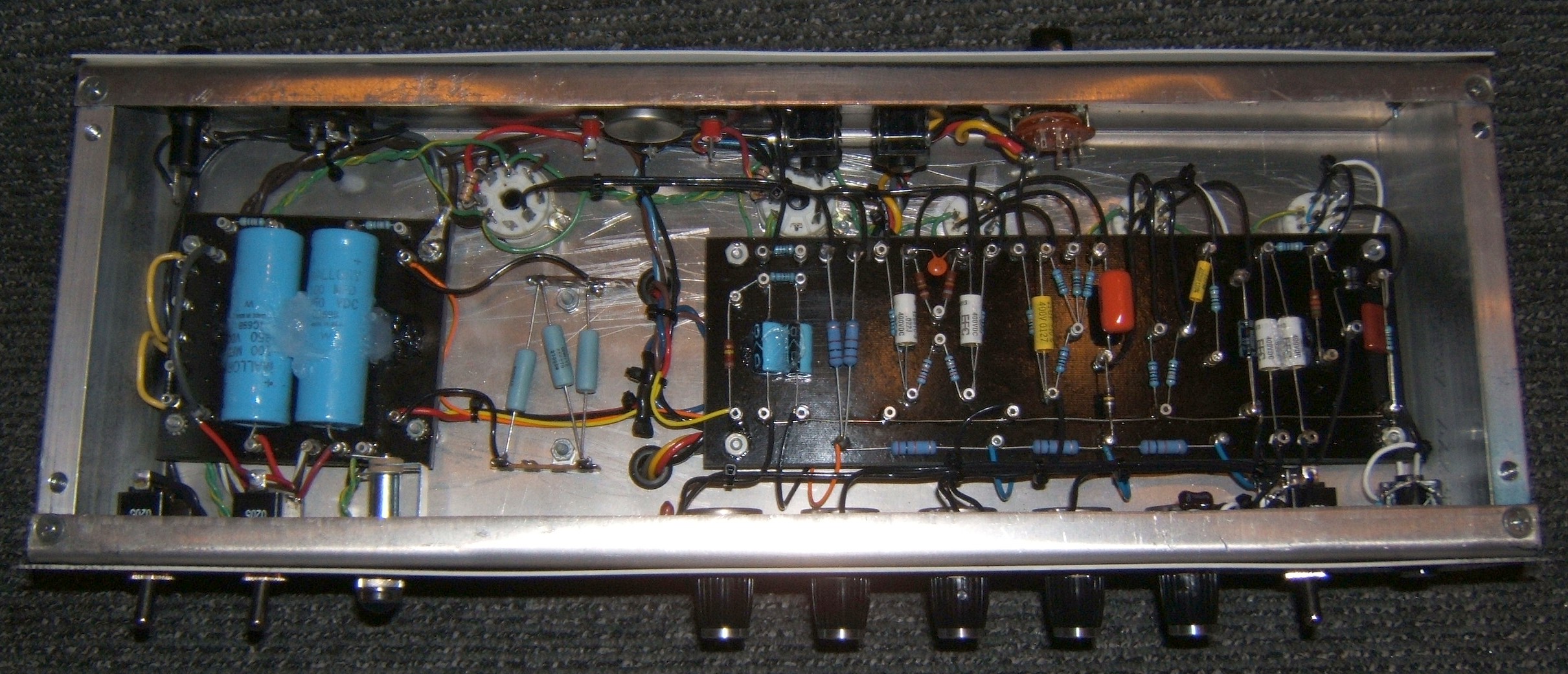
But, the key thing is to keep a tight loop to the first filter cap. So, during the build process, to do so, I always run the CT right to the negative side of the first filter cap, and keep the PT, diodes and cap very close to each other. Like this:
http://paulrubyamplification.com/MartaGuts2.jpg
You can see the red CT line going directly to the negative end of my series filter caps on the PS board. Very tight loop with all components, including stand-by switch very close.
As yours is built, that cap charging current travels from the PT, to the bridge, to the stand-by switch, to the filter cap, to the choke mounting bolt, through the chassis, to the PT mounting bolt, back to the PT. This might be OK if the antenna formed by this loop isn't quite aimed at the critical circuits, so may be fine. But, it's a risk. If you have a buzz problem in this amp, then I would consider this as a potential source of the problem.
I'm being careful to say that what you've done might be just fine to avoid the inevitable reply from someone who happened to choose a risky layout but managed to get good results. Doing something risky doesn't directly mean something bad will happen. But, I prefer to follow the less risky paths when I build so I don't need to re-work when something bad does happen. The picture above represents a method I can say works every time at avoiding the buzz. And is part of a couple other things I do: No grid stopper on the input stage; circuit ground to chassis right at the input jack.
, one less antenna...
