UR12 wrote: ... It weighs a little over 300 lbs...
I stood next to one, yesterday, at our HF store.
It's a BIG BOY
I guess the LASMAC LC1212 will be next
Dana be a amp-designin', chassis-foldin' mo-... uh... uh... fool
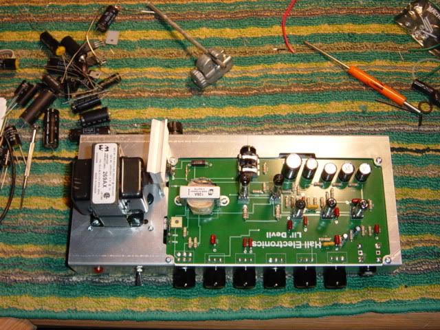
Can anyone tell me the voltage at the PS cap used to supply the LED pilot light? I need this voltage to calculate the current limiting resistor value .....
This is from John.
Gary, I used one of these: Dialight 2VDC LED Mouser #645-608-1131-110F.
Gary, that's a 33K 1/2w dropping resistor from B+ to the LED.
Hope that helps.
Been waiting for Dana to finish up him build guide, W/schematic and all the as you go pictures. Expect his will post his files pretty soon as the next round of kits are probably getting close to going out.
Gary
In the 60's people took acid to make the world weird. Now the world is weird , and they take Prozac to make it normal.
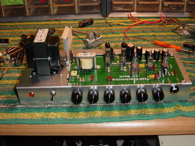
Need to play with bias resistor as range is -40/-50 v. Would like to drop it to -30/-40 range me thinks.
1.5R resistors on filament leads dropped the 7.5v no load voltage to 6.1v. loaded. Will live with that.
Hum balance pot worked gooood. Had some hum and the pot took care of it.
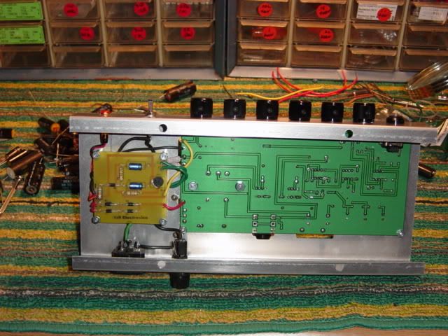
Could not find anything out in the garage....go figure....to use for standoffs for the power board so went to auto parts and got a piece of stainless brake line that fit 4-40 screws and cut my own.
Need to play with bias resistor as range is -40/-50 v. Would like to drop it to -30/-40 range me thinks.
1.5R resistors on filament leads dropped the 7.5v no load voltage to 6.1v. loaded. Will live with that.
Hum balance pot worked gooood. Had some hum and the pot took care of it.
Could not find anything out in the garage....go figure....to use for standoffs for the power board so went to auto parts and got a piece of stainless brake line that fit 4-40 screws and cut my own.
If you have a Grainger supply in town you can get a good deal on standofs and other hardware from them. I use grainger part number 6RB89. They are female 1/4 hex standoffs that are 1/2" tall and accept 4x40 screws. You get a pack of 10 for $3.80. That 68k resistor should get you in the 30- 40 voltbias range.
Gary, thanks for the info.... but... I am using a different LED, so I need the B+ voltage at that PS cap to compute the resistor I will need...
Can you check it with your meter for me???
Also, I've been looking at the bias pot layout on the board and it does not appear to be the same as the real express- the 47K on the Lil Devil is connected to the wiper I think.....
Ron Worley wrote:Gary, thanks for the info.... but... I am using a different LED, so I need the B+ voltage at that PS cap to compute the resistor I will need...
Can you check it with your meter for me???
Also, I've been looking at the bias pot layout on the board and it does not appear to be the same as the real express- the 47K on the Lil Devil is connected to the wiper I think.....
Ron
The B+ on the cap in one I have here is 191 volts. A typical led will drop about 1 to 2 volts. If you use 190v as a round number that the resistor has to drop and you figure the LED current as 12 ma, you will need a 15K resistor. If you go with 20 ma you will need a 9500 ohm (10k). 33k will get you about 6ma. If you calculate the wattage at 6ma you get 1.14 watts. A 2 watt resistor here should be fine.
The LED and resistor also serves as a bleeder to drain the caps when you turn the amp off. Since there is no standby switch you can turn down the "Power" to put the amp in standby or if you just flip the power switch the LED goes from bright to a dim glow that gets dimmer until the caps are discharged and then it goes completely out. The real Express bleeder resistors are 2 100k resistors connected to about 400v. They draw about 2 ma and need to dissipate .8 watts.
The bias pot has the wiper and one leg tied together and that goes to the 47k. The other leg goes to ground so when you adjust the pot you have a range of between 47k and 72k to ground. This functions exactly the same as an Express but doesn't leave one leg of the pot dangeling in thin air. Just a personal preference
I would say most of this amp doesn't appear to be the same as a real Express
I always ground the third leg on my Express as well, I was looking at an old version of my express layout that I had mis-labeled the wiper position. It's all good at this point!
I really like the bleeder aspect of the LED, it's a good safety thing and a good way to know when it's all bled off....
grizz wrote:I'm assuming that's the speaker jack on top and in the back of the PCB?
That seems like a funny place for it?
Scott
Hi Scott
Yes, that is the speaker jack
Do you think I should have put it on the front of the amp?
Honestly, I was trying to keep as much of the amp on the PCB as possible and as one unit . I could have mounted it to the bottom of the board but then it would have been impossible to install the board in the chassis (Unless I went with a 2 piece chassis) after all of the parts were mounted on the board and I would have had to shorten the width of the chassis to about 4 inches. I also thought about making the jack part of the board that could be snapped off and installed in the back of the chassis but finally decided that this was the best all around solution. They are only 2 PCBs in this amp and less than 12 wires to run. There is nothing stopping anyone from mounting the speaker jack on the back of the chassis and running wires to it if that suits your fancy. I think John actually mounted his that way. My goal was to try and make this as easy as I could for a first time builder to build the amp without having to worry about running a bunch of extra wires from the board to different places or twisting heater wires. It should make a great first time project for someone wanting to build their first amp.
That's looking great! Have you fired it up yet? can't wait to hear your impressions.
A little update on the kit's progress
I have been scouring the world for the parts for the Lil Devil Kits and I think I have found the dual pots that are made to fit the board for the Power control (VVR). I will know when they get here. I also picked up some jacks (Cliff style) for the speaker jack we were discussing above that lifts it off of the board about an extra 1/8 of an inch. This will make it possible to use a right angle plug in addition to a regular 1/4 iplug. It will also make it easier to make a bracket to mount the jack to the chassis.
The new batch of boards are shipping out on the 2/23 and I will have them by the 26th (if not sooner). I have made a few adjustments to a the parts on the main board but it is 97% the same as the prototypes. I also had a Power supply PCB manufactured and it has provisions for the LED current limiting resistor on the PS board and brings a couple of pads near the LED so that two wires only need to be run. I think you could solder on one of the pig tail connecters they use for computer mother boards to connect the panel LEDs or switches to the board. This would keep you from having to solder wires onto the leads of the LED.
I was having a PM conversation with Gary on the hum balance setup he has so that I can include those parts in the BOM....
I have to show my ignorance here.... but if you are using the Heyboer trannys with the CT, is a hum balance even needed???
Gary used a 594-63X201 trimmer pot (don't know the value) and 2 660-MOSX3CT631RR15J .1R 3W metal film resistors (both are Mouser part numbers). Normally, an artificial CT uses 100R, so what is it that I am missing here- these seem like really low value R resistors....


