Started DClone

Overdrive Special, Steel String Singer, Dumbleland, Odyssey, Winterland, etc. -
Members Only

Moderators: pompeiisneaks, Colossal

User avatar
Bob-I
Posts: 3791
Joined: Thu Feb 02, 2006 10:06 pm
Location: Hillsborough NJ

Re: Little Help Please

Post by Bob-I »

Blues Hound wrote:Well, everything is done, voltages at V1, V2, V3 area fine:

V1 CL1 and CL2:
Pin 1 = 185 VDC
Pin 2 = 0.7 mv
Pin 3 = 1.794 VDC
Pin 6 = 185 VDC
Pin 7 = 0.7 mv
Pin 8 = 1.798 VDC

V2 OD1 and OD2:
Pin 1 = 211 VDC
Pin 2 = 0.7 mv
Pin 3 = 1.518 VDC
Pin 6 = 212 VDC
Pin 7 = .06 mv
Pin 8 = 1.509 VDC

V3 PI:
Pin 1 = 293 VDC
Pin 2 = 37.8 VDC
Pin 3 and Pin 8 = 60.3 VDC
Pin 6 = 294 VDC
Pin 7 = 38.7 VDC

V4 Reverb:
Pin 1 = 442 VDC
Pin 2 = 4.4 mv
Pin 3 = 3.24 VDC
Pin 6 = 171.7 VDC
Pin 7 = 0.1 mv
Pin 8 = 1.99 VDC

But I seem to have a problem with the 12v supply to the relays.

Here is a picture of the board:

[img:1024:768]http://i394.photobucket.com/albums/pp25 ... edo013.jpg[/img]

[img:1024:768]http://i394.photobucket.com/albums/pp25 ... edo026.jpg[/img]

It is basically the same board as #124, but I am only getting .526 VDC at the output on the 12 v regulator...any help is greatly appreciated...

Steve
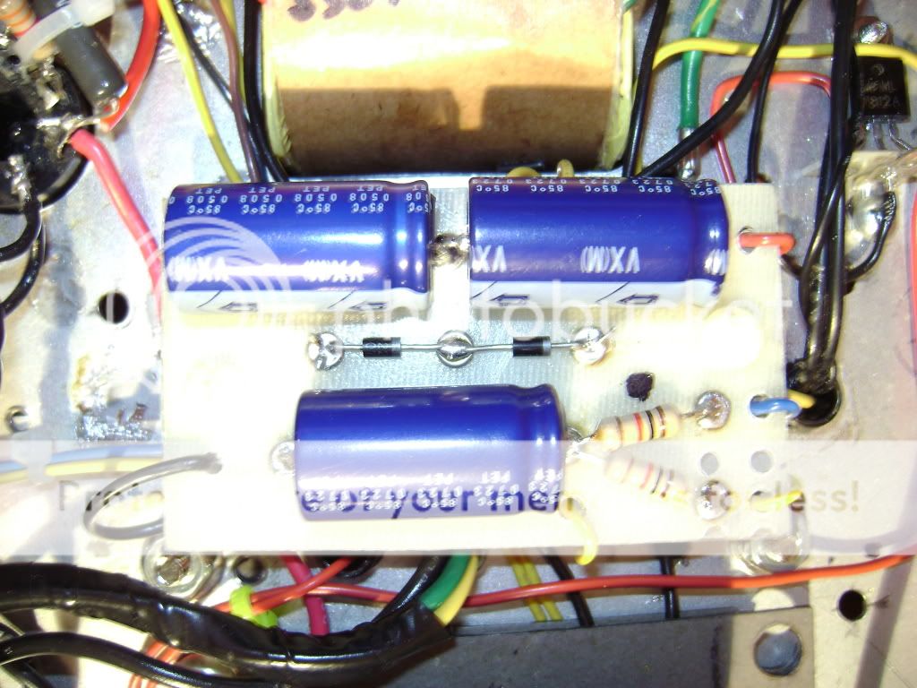
I can't follow the entire schematic through the pics, but make sure you compare the board vs schematic. The Red/Red wires from the xformer should go one between the diodes and one between the first 2 100uF caps. Check the AC voltage at this point, then follow though by checking a the input of the regulator, the grounding of the regulator and of course the out. It's a voltage double so it's a tad odd.

nice job on the amp.
Blues Hound
Posts: 143
Joined: Sun Apr 09, 2006 1:58 am

Re: Started DClone

Post by Blues Hound »

Bob,

That is exactly how I did it, the one yellow wire from the transformer going to the eyelet between the 1000uf caps and the second going to the eyelet between the diodes...maybe the transformer is bad... :?

So close...and yet so far away... :cry:

Steve
JimiB
Posts: 359
Joined: Sat Jun 04, 2005 9:03 pm

Re: Started DClone

Post by JimiB »

where is the 12V coming from? If you dissconnect those leads do you have 12V on them?
Blues Hound
Posts: 143
Joined: Sun Apr 09, 2006 1:58 am

Re: Started DClone

Post by Blues Hound »

JimiB,

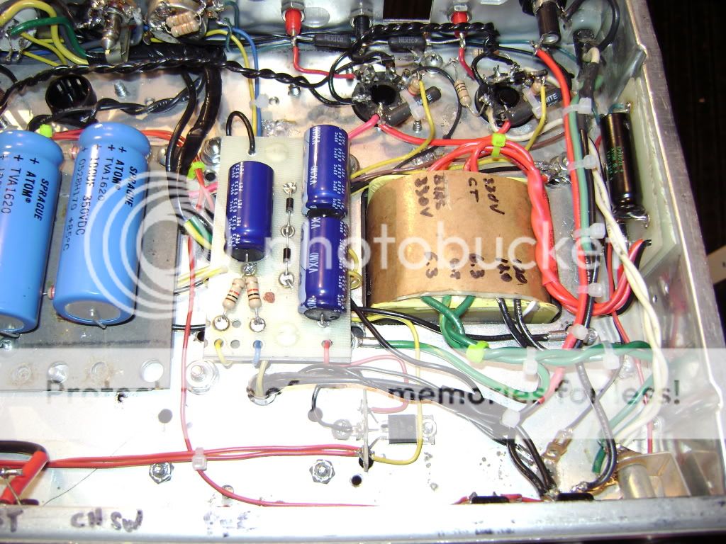
I have a Radio Shack Transformer, #273-1365, mounted on bottom of the chassis, if you look at the bottom picture you can see the two black wires(120V) and the two yellow wires (12v) coming up through the groumet below the Blue wire of the borad.

I have one of the black wires going to the Standby Switch and the other going to the Fuse holder at the back of the amp.

I was following the #124 schematic and layout.
Pete
Posts: 272
Joined: Mon Mar 06, 2006 4:01 pm
Location: 444547N 0853714W (approx)

Re: Started DClone

Post by Pete »

Blues Hound wrote:I have one of the black wires going to the Standby Switch and the other going to the Fuse holder at the back of the amp.
Are you sure you mean Standby Switch? That can't be right. (black wires = primary)
Blues Hound
Posts: 143
Joined: Sun Apr 09, 2006 1:58 am

Re: Started DClone

Post by Blues Hound »

Pete,

The primaries for the 12v transformer are attached to the same lugs as the primaries from the PT, the Fuse holder and the Mains Switch (not the Standby Switch really tried when I posted that) that is my understanding where they go.

Steve
User avatar
Bob-I
Posts: 3791
Joined: Thu Feb 02, 2006 10:06 pm
Location: Hillsborough NJ

Re: Started DClone

Post by Bob-I »

Blues Hound wrote:Pete,

The primaries for the 12v transformer are attached to the same lugs as the primaries from the PT, the Fuse holder and the Mains Switch (not the Standby Switch really tried when I posted that) that is my understanding where they go.

Steve
The question then is do you have the 6V AC coming from the relay xformer? Measure at the input of the relay PS board.
Blues Hound
Posts: 143
Joined: Sun Apr 09, 2006 1:58 am

Re: Started DClone

Post by Blues Hound »

Bob-I,

Will check tonight when I get home and post.

Steve
Blues Hound
Posts: 143
Joined: Sun Apr 09, 2006 1:58 am

Re: Started DClone

Post by Blues Hound »

120VAC on 12v transformer primaries and 0.00 VAC from the transformer outs :cry:

Guess I need to replace it...
Blues Hound
Posts: 143
Joined: Sun Apr 09, 2006 1:58 am

Re: Started DClone

Post by Blues Hound »

Put in the new 12v Transformer, I am getting 7.23 VAC and 7.18 VAC on the secondaries.

Re-attach them into the 12V Power Supply Board, one bteween the 1000uf caps and one between the diodes...measure the output 0.00 VDC???

Unsolder them, re-measure - 7.23 VAC and 7.18 VAC.

Not sure what to do now.
User avatar
heisthl
Posts: 1800
Joined: Fri Sep 29, 2006 5:35 am
Location: Phoenix

Re: Started DClone

Post by heisthl »

The board is layed out as a voltage doubler and the schematic calls for a 6.3 volt transformer, the 12 volt transformer should work because the 7812 should handle up to 30 volts in, still it is possible that the 7812 regulator is fried. It is more likely that it's something simpler like maybe your transformer has a center tap and you're grounding it - a definite no no. Try it without the regulator connected and see if you still get 0.
Former owner of Music Mechanix
www.RedPlateAmps.com
Blues Hound
Posts: 143
Joined: Sun Apr 09, 2006 1:58 am

Re: Started DClone

Post by Blues Hound »

The center tap is not being used, I do have another 7812 and will try replacing that.

Is there a different board to use for the 12 v transformer?
User avatar
heisthl
Posts: 1800
Joined: Fri Sep 29, 2006 5:35 am
Location: Phoenix

Re: Started DClone

Post by heisthl »

Here is an alternate schematic - used in many of the amps you see on this forum.
You do not have the required permissions to view the files attached to this post.
Former owner of Music Mechanix
www.RedPlateAmps.com
Blues Hound
Posts: 143
Joined: Sun Apr 09, 2006 1:58 am

Re: Started DClone

Post by Blues Hound »

Well she is finished :D

Switching works, although the output to the 7812 is 35 VDC, need to build a new board for that.

Couldn't really put her through her paces, but at low volumes, she sounds very good :D

Will post pictures and voltages tommorow.

Thanks to everyone for their help.
User avatar
heisthl
Posts: 1800
Joined: Fri Sep 29, 2006 5:35 am
Location: Phoenix

Re: Started DClone

Post by heisthl »

Blues Hound wrote:Well she is finished :D

Switching works, although the output to the 7812 is 35 VDC, need to build a new board for that.

Couldn't really put her through her paces, but at low volumes, she sounds very good :D

Will post pictures and voltages tommorow.

Thanks to everyone for their help.
Why not just use the center tap and one of the outside legs (tape the other one off). The 7812 will thank you.
Former owner of Music Mechanix
www.RedPlateAmps.com
Post Reply