Rocket tone control values
Moderators: pompeiisneaks, Colossal
Rocket tone control values

Re: Rocket tone control values
Yes I'm confused as well - Mark Abbott's schemo shows some different values to his layout and another schemo just has the Vox values? There are also some pictures of Paul Ruby's Rockets that show some further different values? 
-
tubedogsmith
- Posts: 597
- Joined: Mon Jan 17, 2005 11:52 pm
Re: Rocket tone control values
If you use the .002 mid cap then use a 500pf for the treble cap, there was at least one real rocket with these values. The PI cathode resistor is 1.2k, the tail is 47k. This tone stack combo gives you a real strong mid tone with more apparent gain. It also sounds cool in a liverpool.
Re: Rocket tone control values
Re: Rocket tone control values
Sounds interesting, I've just removed a 500p from my Lightning because it was somewhat under-whelming. I'll give the 500p/0.02u/0.002u a try. Thanks for posting!tubedogsmith wrote:If you use the .002 mid cap then use a 500pf for the treble cap, there was at least one real rocket with these values. The PI cathode resistor is 1.2k, the tail is 47k. This tone stack combo gives you a real strong mid tone with more apparent gain. It also sounds cool in a liverpool.
Re: Rocket tone control values
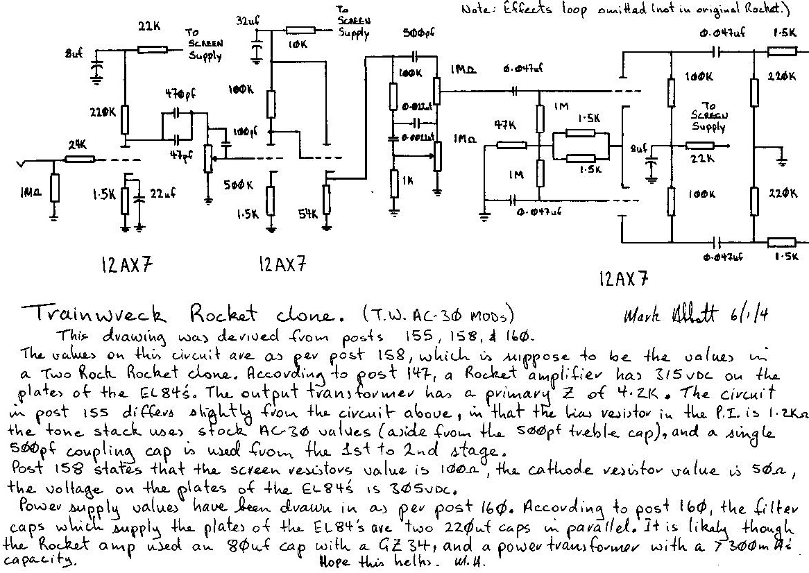
Here are some things to think about. Download a copy of Duncan's Tone Stack Calculator, if you haven't already. Mark mentions 2 different Rocket tone control configurations. Reading his notes, the values on the schematic are from a 2-Rock clone (?!?!).
Okay, plug the 2-Rock values into the Vox tab on the calculator: it's a very middy response. It looks kind of strange for a tone stack but okay.
On Mark's schematic, he also mentions another tone stack configuration in the notes. This is just an AC30 top boost tone stack with a 470p subbed for the 47p treble resistor. Plug this into tone stack calculator. Now plug the Express "Kelly" values (470p/100k/22n/22n/1M/1M/25k) into the calculator on the Fender tab. Switch between the Fender and Vox tabs.
The frequency response of the 2nd Rocket tone stack configuration that Mark mentioned is almost exactly the same as the Twreck Kelly values. The Kelly stack is a little less lossy but the curves are nearly identical.
I don't really know what all this means, I just thought it was interesting...

Re: Rocket tone control values
What do you think?! 
Re: Rocket tone control values
I'm not sure what I think but I'm going to find out. I've played with subbing a 470p for the 47p in the Vox tone stack in amp prototypes and pedal circuits. It adds a nice upper midrange kick that I liked. I'm getting ready to mod my Firefly into a "baby Rocket" and I'm going to try both the tone stacks and see which one I like better. That's what got me looking into this.
Re: Rocket tone control values
Downloaded the calculator and had a play. Lines on a graph very musical 
 However my peanut brain finally caught up with "Hey Nick! why don't you see what the response looks like for the stack settings youve been using on your AC30 for the last 30 years?"
The result is the "normal" vox settings give a flat frequency response but attenuated by about 25dB. Interesting...
Now if you plug in the Rocket values suddenly you are getting the same flat response but attenuated 42dB. The main driver of the attenuation is the 10K/1K mid resistor.
The result is the "normal" vox settings give a flat frequency response but attenuated by about 25dB. Interesting...
Now if you plug in the Rocket values suddenly you are getting the same flat response but attenuated 42dB. The main driver of the attenuation is the 10K/1K mid resistor.
You do not have the required permissions to view the files attached to this post.
Re: Rocket tone control values
I don't understand your plots. All you changed was the 10k and the output load, which IMO should be the same between the Rocket and AC30. I think the PI's of the two amps are roughly the same circuit. If you use the 1k in the Rocket circuit, C1 should be a 2.2n and C2 should be 470p.
This is what I found with the tone stack calculator:
This is what I found with the tone stack calculator:
You do not have the required permissions to view the files attached to this post.
Re: Rocket tone control values
Re: Rocket tone control values
Doug H wrote:I don't understand your plots. All you changed was the 10k and the output load, which IMO should be the same between the Rocket and AC30. I think the PI's of the two amps are roughly the same circuit. If you use the 1k in the Rocket circuit, C1 should be a 2.2n and C2 should be 470p.
This is what I found with the tone stack calculator:
In this configuration you get -25db attenuation for the Vox and -42db for the Rocket with the flat response shown. Changing the 56k cathode-follower resistor to 68k makes +/- 1dB difference so it's probably inaudible. Note that we are assuming this calculator is actually correct in its output.
I changed the output load because the Rocket has 220k into 1M. BTW this made pretty much no difference to the response curve.
What all the above indicates (to me at least) is that the Vox frequency response (as used by Vox players) is more to do with coupling caps than the tone stack. If you replaced the tone stack with a pad you'd (well I'd
BTW it is interesting that you are so definitive regarding what values should or shouldn't be used in a Rocket tone stack. I'll read back through the various threads but I haven't seen anything "definitive" about the rocket - perhaps I missed it
Re: Rocket tone control values
We must be looking at 2 different schematics. I'm referring to Mark's Rocket schematic in the "Trainwreck Files" section of this board https://tubeamparchive.com/files/Mark_R ... fo_cct.jpg . There's no "220k into 1M" and the cathode follower resistor is not 68k. I'm going by his notes which outline 2 tone stacks that were seen. I plugged both of them into the TSC and made an observation. The only tone stack change you made was the 1k/10k swap (compared to the AC30) when there were other changes Mark outlined in his notes. Again, maybe we're looking at 2 different schematics?
I never claimed anything was "definitive". In fact I did say "I don't really know what all this means" and "I'm not sure what I think but I'm going to find out" and "I'm going to try both the tone stacks and see which one I like better". Maybe you haven't really read my responses.
I agree that if you are running bass and treble on zero, it makes the tone stack pretty useless. Why not just use the normal channel? Maybe the top boost channel has tighter bass.
Re: Rocket tone control values
Yes I think we may be. Trouble is that when you look on Mark's rocket layout he has the 68K and 220k resistors. Plus the 10k Mid resistor and 50pF and 0.022u x 2 tone caps. Theres' yet another schematic somewhere which is different again and, as I say in a post above, Paul Ruby's rocket clones seem to have further differences.Doug H wrote:We must be looking at 2 different schematics. I'm referring to Mark's Rocket schematic in the "Trainwreck Files" section of this board https://tubeamparchive.com/files/Mark_R ... fo_cct.jpg . There's no "220k into 1M" and the cathode follower resistor is not 68k. I'm going by his notes which outline 2 tone stacks that were seen. I plugged both of them into the TSC and made an observation. The only tone stack change you made was the 1k/10k swap (compared to the AC30) when there were other changes Mark outlined in his notes. Again, maybe we're looking at 2 different schematics?
Possibly not but you did say "If you use the 1k in the Rocket circuit, C1 should be a 2.2n and C2 should be 470p." which sounds pretty definite to meI never claimed anything was "definitive". In fact I did say "I don't really know what all this means" and "I'm not sure what I think but I'm going to find out" and "I'm going to try both the tone stacks and see which one I like better". Maybe you haven't really read my responses.
Also an extra gain stage, cathode follower, lower coupling cap and bright cap on the vol pot. None of those are actually reasons of course. The reason is "hey that sounds more gooder!"I agree that if you are running bass and treble on zero, it makes the tone stack pretty useless. Why not just use the normal channel? Maybe the top boost channel has tighter bass.
The really interesting thing for me is that I've found out something about my rig that I didn't know before that almost makes sense. So thanks for posting the pointer to the Duncan site.
Re: Rocket tone control values
Yeah, I see what you mean. There are a lot of differences between component values in Mark's schematic and layout for the Rocket. I had not looked at the layout. My guess is that you probably don't need the 220k. IIRC, the AC30's used 220k mixer resistors when connecting the normal and top boost channels to the PI.Trouble is that when you look on Mark's rocket layout he has the 68K and 220k resistors. Plus the 10k Mid resistor and 50pF and 0.022u x 2 tone caps. Theres' yet another schematic somewhere which is different again and, as I say in a post above, Paul Ruby's rocket clones seem to have further differences.
Yeah well, I was just referencing Mark's schematic and notes. I didn't realize his layout differed. Maybe that was the source of the misunderstanding.Possibly not but you did say "If you use the 1k in the Rocket circuit, C1 should be a 2.2n and C2 should be 470p." which sounds pretty definite to me
I thought about that too. I wonder if the extra stage and follower make that much difference if the tone stack is that lossy.Also an extra gain stage, cathode follower, lower coupling cap and bright cap on the vol pot.
That's the bottom line. None of the other stuff really matters.The reason is "hey that sounds more gooder!" Very Happy
I've played around with the top boost tone stack quite a bit. I can say that just subbing a 470p for the 47p and leaving the rest of it stock sounds pretty "Ken-y" to me-Big gain boost in the upper mids. I'm not saying that's what he did in the Rocket. It's always worth it to try a lot of different ideas.
Also, if you want more gain try increasing or removing the 10k. Did you know the original top boost tone stack was a mistake? There's a nice article about it out there somewhere. The idea came from a Gibson amp. Try moving the 10k from the bass pot wiper to the end lug that is grounded. Insert the 10k between the pot lug and ground. This gives you a basic TMB tone stack like Marshall/Fender.
Lots of fun to be had...