Didn't want to be warned for multi-posting so I answered everyone at once.
I'm looking for help in choosing a layout, placement and type of terminals/turrets/eyelets for my Circuit Rebuild using discrete components.
Yeah! A CLASSIC Video from Brad the Guitologist!
Love this guy! I'm an avid fan of his!
And what a legendary 4 parter Video Series!
The Saga of Ahab slaying his Whale!
I had seen it previously, but probably because I was so focused on the mystery behind the Mesa's malfunction, I didn't register in my long term memory his rebuilding of the EL84's Power Tubes Daughter Board with discrete components!
If anyone needs proof of how and why this Board with PCB mounted Sockets with critical components located very close by and the Hi-Voltages + Extremely high Temperatures
of Mesa's Dyna-Watt EL84's amps that most often run at/or over 100% Dissipation Rate (I think the Subway Blues was 120%

) is such a huge Potential Failure Point, just tell them to watch Brad's video!
He doesn't go into the 100%+ Plate Dissipation Rate issue, but mentions a great many times the fact that he had changed Components Values to significantly lower the Bias to bring it down to the Goldilocks Zone of ~70%.
While helpful seeing Brad's rebuilt of the Power Tubes Circuit, sadly he just skipped ahead so we didn't get to see him build it nor make his usual comments explaining what he's doing + giving a ton of helpful info...
The end result is not so hard to see, but it's also not super clear. Add the fact that he was missing some Resistors so he used some additional parts to get in the ballpark of the original value, adding some cluttering, and also that he barely used Soldering Terminals and really went classic PTP makes this much less useful to me regarding my questions about how to make a good layout...
I won't make a Rat's Nest or Spaghettis... I'll make it clean, tidy, clear visually so identifying & servicing will be a breeze while still being efficient by not using unnecessary lengthy wires as is often the case when someone builds a circuit with the intention of doing it clean, using Terminals (Lugs, Dual Terminals), Eyelets, Turrets, etc..
I'd still like your input on how you would build the thing while keeping in mind the elements I mentioned. What type of "hubs" would you use (Lugs Terminal, Turrets, etc.)? What about the supporting structure and where would you locate the components?
ChopSauce wrote: ↑Thu May 27, 2021 7:14 am
So what are you trying to achieve: prevent possible failures for the future?
EXACTLY.
Mesa has built many amp models in that era that used the same design flaw, using a PCB Daughter Board on which the EL84 tube sockets are mounted, along with a few critical components.
And since Mesa runs those Dyna-Watts amps insanely hot (usually over 100% plate dissipation rating, some as high as 120% !!!), meaning that the Power Tubes run extremely hot (and since heat rises & the Sockets are located directly onto the PCB, the Board is heated up too) and that there are High Voltages running on the PCB...
It's no mystery why this is a common failure point on those amps, and very often the source of other damages...
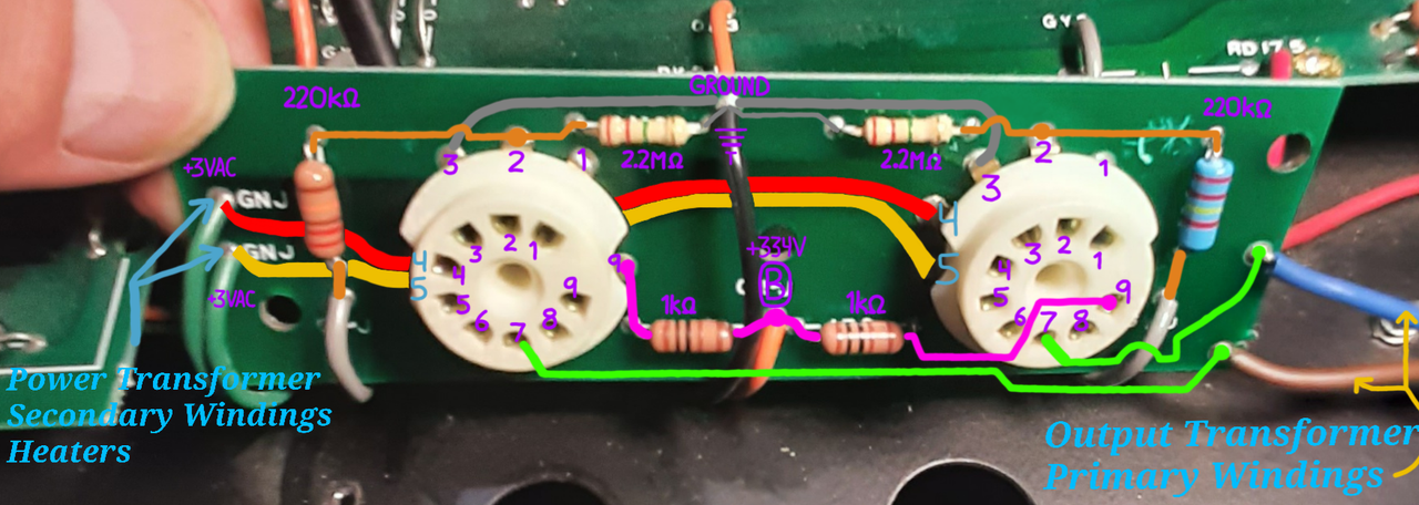
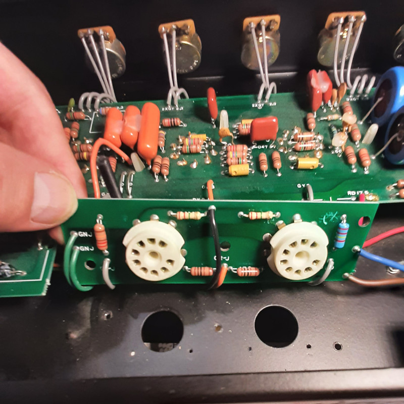
On the Daughter Board:
~> I measured again and found out that
BOTH 2.2M Resistors are bad. They measure around 450-500k for one and 500-550k for the other...
~> The 220k Grid Resistor (the Blue one) on the right has previously been replaced too...
When the amp "blew up" a while ago, it took 6 High Voltage Power Supply Resistors with it! They are all bulged up and look cooked, burnt and black.
(On the Schematic: The chain of 6 Resistors (3x820 & 3x1k) in the Hi-V Supplies section, right above this title.)
I'd stored my amp at my mom's for a few years.One day she came to me and said that she got my amp fixed as a Christmas gift. I learned that she had brought it to an Electric Appliances Repair Store which also dabbles in Electronics...
When I learned of this, the 30 days warranty on the work had expired, the 160-180$ bill didn't give any details except "time worked" and the price charged for a new pair of Electro-Harmonix EL84's from Thetubestore (60$ !), and the amp still didn't work properly.
The tubes, of course, were & still are fine. Until recently, I thought that the only thing that they did was scam my mom for a pair of EL84's, but I saw that they had replaced the 220k Grid Resistor on the PCB.
So, while I'll be replacing the Power Supply Resistors and testing every single component in the amp, I'll rebuild the Power Tubes Sockets Circuit with discrete components to replace the bad 2.2M Resistors and greatly mitigate the overheating issues.
~★~ ~★~ ~★~
I'd like to state that I have the necessary skills, knowledge and experience to solder components neatly both PTP and on a PCB...
~★~ ~★~ ~★~
Thanks guys for your help so far, you are all wonderful!
~> Phil_S has given some warranted constructive feedback.
I thank him for his contribution, his concern and the fact that he advocates caution.
There is a great deal I can learn from him and you all.
~★~ ~★~ ~★~
In my next post, I'll show some pictures of layouts and wiring I have found that look interesting, and I'll ask your opinion on those!
I'm really looking forward to hearing from you all and go back to having a normal discussion with you!
Take care!