Starting on another build, keepin' them rolling!
I have this Sundown Formula 50, which I have stripped and rebuilt a couple times now.
The chassis has presented some challenges; the holes on the right are meant for preamp tubes (sockets were originally PCB mounted), but they're too large to mount regular sockets directly to the chassis.
I had decided on creating a floating plate that would hold the preamp tube sockets, but I've realized those holes are actually correct for octal sockets.
So now I'm thinking about moving the power tubes to that location, drilling new 3/4" holes for preamp tubes, and maybe using can caps in the original power tube socket locations.
Anyway, I've done a bunch of Fender-y classic designs, relatively low gain. I'm wanting to try something higher gain now, and I'm liking the look of the Soldano SL60
First off, a couple questions about that schem;
1) The filament winding is shown with both a center tap, and an artificial tap. Is there some purpose for this? I understood it to be an either/or situation.
2) The HT winding is shown with both a center tap, but also has a full wave bridge rectifier. My understanding was that FWBR was for HT windings without a CT. Is there a reason why you would go with a bridge rectifier even if the HT winding has a CT?
3) The sundown didn't use a choke, so I was looking at the Hammond 159P (10H, 125mA, 500V). I expect about 450V on the plates, is that cutting to close to the choke max voltage?
Love y'all hope everyone is safe, thanks!
Choke for soldano build, and some other questions.
Moderators: pompeiisneaks, Colossal
-
turbofeedus
- Posts: 205
- Joined: Wed Jan 30, 2019 5:37 am
Choke for soldano build, and some other questions.
You do not have the required permissions to view the files attached to this post.
-
Stevem
- Posts: 5144
- Joined: Fri Jan 24, 2014 3:01 pm
- Location: 1/3rd the way out one of the arms of the Milkyway.
Re: Choke for soldano build, and some other questions.
I would ditch the 100 ohm filament resistors and run a Fender type hum trim pot so you can adjust the least amount of 60 HZ hum.
The diode bridge and the center tap of the ht winding need that ground reference.
Where are you planing to wire in the choke to the power supply, after the output tube plate feed?
The diode bridge and the center tap of the ht winding need that ground reference.
Where are you planing to wire in the choke to the power supply, after the output tube plate feed?
When I die, I want to go like my Grandfather did, peacefully in his sleep.
Not screaming like the passengers in his car!
Cutting out a man's tongue does not mean he’s a liar, but it does show that you fear the truth he might speak about you!
Not screaming like the passengers in his car!
Cutting out a man's tongue does not mean he’s a liar, but it does show that you fear the truth he might speak about you!
-
turbofeedus
- Posts: 205
- Joined: Wed Jan 30, 2019 5:37 am
Re: Choke for soldano build, and some other questions.
That's fine, and to be sure, I would just leave the filament CT disconnected right?
That makes sense, but is there some benefit to using a bridge rectifier if you have a CT?
Yes, basically just as it's shown in the soldano schematic
-
thetragichero
- Posts: 478
- Joined: Tue Sep 10, 2019 7:46 pm
Re: Choke for soldano build, and some other questions.
you'd use a bridge (VDC = 1.4xVAC) when the full wave rectification (VDC = 0.7xVAC) wouldn't provide the appropriate B+ you're looking forturbofeedus wrote: ↑Wed Oct 14, 2020 5:21 pm
That makes sense, but is there some benefit to using a bridge rectifier if you have a CT?
PRR wrote: Plotting loadlines is only for the truly desperate, or terminally bored.
-
turbofeedus
- Posts: 205
- Joined: Wed Jan 30, 2019 5:37 am
Re: Choke for soldano build, and some other questions.
Ah, I see. So I just measured the PT from the sundown, it's 335-0-335VAC. In this case I would want to continue to use full wave rectification, because the bridge rectifier would put my B+ at ~950V unloaded.thetragichero wrote: ↑Wed Oct 14, 2020 5:30 pm
you'd use a bridge (VDC = 1.4xVAC) when the full wave rectification (VDC = 0.7xVAC) wouldn't provide the appropriate B+ you're looking for
The soldano HT must have been spec'd lower, like 150-0-150VAC.
So I was mistaken that bridge vs full wave is strictly a matter of whether the HT winding is center tapped. While you still must use a bridge rectifier when the HT winding doesn't have a center tap for ground reference, you can use a bridge rectifier with a lower spec'd HT winding if it suits your B+ requirements.
-
pompeiisneaks

- Site Admin
- Posts: 4244
- Joined: Sat Jan 14, 2017 4:36 pm
- Location: Washington State, USA
- Contact:
Re: Choke for soldano build, and some other questions.
For the filaments, you would use a potentiometer at say 200 ohms that puts each lead into the left/right sides and ground the center of the pot. That allows you too vary the resistance between say 60/140 between the sides etc, so you can balance out the transformer to optimal hum balance. It's a nice way of ensuring that you get the quietest hum from the heatersturbofeedus wrote: ↑Wed Oct 14, 2020 5:21 pmThat's fine, and to be sure, I would just leave the filament CT disconnected right?
That makes sense, but is there some benefit to using a bridge rectifier if you have a CT?
As for the rectifier, you have to choose which you're going to use. They output different voltages.
full wave (FW) rectified is like .9X the input voltage, but full wave bridged (FWB)(ground referenced) puts out 1.4 times the input voltage.
So you could say have a 300 - 300 that's going to run at 270VDC on the output with a bridge rectifier, and if using a FWB it would be 450VDC instead, quite a difference in B+ and you need to know what you're shooting for. If the amp was designed to use the FWB, then it needs it or you'll be way under voltage for the expected amp.
~Phil
tUber Nerd!
-
turbofeedus
- Posts: 205
- Joined: Wed Jan 30, 2019 5:37 am
Re: Choke for soldano build, and some other questions.
Thanks Phil, my confusion really is why it's drawn (and supposedly wired) with both an artificial center tap, and with an actual center tap in the transformer. I thought the artificial center tap was installed specifically when there was no filament CT.pompeiisneaks wrote: ↑Wed Oct 14, 2020 6:04 pm
For the filaments, you would use a potentiometer at say 200 ohms that puts each lead into the left/right sides and ground the center of the pot. That allows you too vary the resistance between say 60/140 between the sides etc, so you can balance out the transformer to optimal hum balance. It's a nice way of ensuring that you get the quietest hum from the heaters
Yes, so in my case if I want to hang around the original B+ numbers from the Sundown (mid 400's), I want to stick with full wave rectification as the Sundown was. Otherwise I will end up with much higher B+. That makes sense.pompeiisneaks wrote: ↑Wed Oct 14, 2020 6:04 pm As for the rectifier, you have to choose which you're going to use. They output different voltages.
full wave (FW) rectified is like .9X the input voltage, but full wave bridged (FWB)(ground referenced) puts out 1.4 times the input voltage.
So you could say have a 300 - 300 that's going to run at 270VDC on the output with a bridge rectifier, and if using a FWB it would be 450VDC instead, quite a difference in B+ and you need to know what you're shooting for. If the amp was designed to use the FWB, then it needs it or you'll be way under voltage for the expected amp.
~Phil
-
thetragichero
- Posts: 478
- Joined: Tue Sep 10, 2019 7:46 pm
Re: Choke for soldano build, and some other questions.
you've pretty much got it, but also note that if you've got a non-center tapped ht secondary you can also use a voltage doubler like the old bogen pa amps often did
PRR wrote: Plotting loadlines is only for the truly desperate, or terminally bored.
-
turbofeedus
- Posts: 205
- Joined: Wed Jan 30, 2019 5:37 am
Re: Choke for soldano build, and some other questions.
Understood, thanks.thetragichero wrote: ↑Wed Oct 14, 2020 6:41 pm you've pretty much got it, but also note that if you've got a non-center tapped ht secondary you can also use a voltage doubler like the old bogen pa amps often did
Another question about the schematic, the bias pot is 47K. I imagine it might be difficult to dial in a bias adjustment with that large of a pot.
I know I could just alter the values of the two resistors either side of the part to narrow down the sweep, but I wonder if a multi-turn pot could also work?
If I could find a 50k 10 turn pot, that should allow more precise tuning of the bias point no?
Re: Choke for soldano build, and some other questions.
A 10 turn pot would be more precise but I've never had any difficulty setting bias accurately with a 50K pot. I've used this pot on several builds...
http://sluckeyamps.com/6v6plexi/P-6V6_05_big.jpg
http://sluckeyamps.com/6v6plexi/P-6V6_05_big.jpg
-
turbofeedus
- Posts: 205
- Joined: Wed Jan 30, 2019 5:37 am
Re: Choke for soldano build, and some other questions.
Alright cool, I'll give the 1 turn pot a try.sluckey wrote: ↑Wed Oct 14, 2020 9:12 pm A 10 turn pot would be more precise but I've never had any difficulty setting bias accurately with a 50K pot. I've used this pot on several builds...
http://sluckeyamps.com/6v6plexi/P-6V6_05_big.jpg
-
turbofeedus
- Posts: 205
- Joined: Wed Jan 30, 2019 5:37 am
Re: Choke for soldano build, and some other questions.
Hold up, is the DCCF coming out of the effects loop wrong on the schematic?
Is it possible to input to the cathode like this?
I'm looking at other schematics, surely the 1K should be the cathode resistor on the first stage, 1M grid leak, and the 100K plate resistor on the first stage as well?
Is it possible to input to the cathode like this?
I'm looking at other schematics, surely the 1K should be the cathode resistor on the first stage, 1M grid leak, and the 100K plate resistor on the first stage as well?
You do not have the required permissions to view the files attached to this post.
-
turbofeedus
- Posts: 205
- Joined: Wed Jan 30, 2019 5:37 am
Re: Choke for soldano build, and some other questions.
Yeah pretty sure that recovery stage after the effects loop is wrong on the schematic.
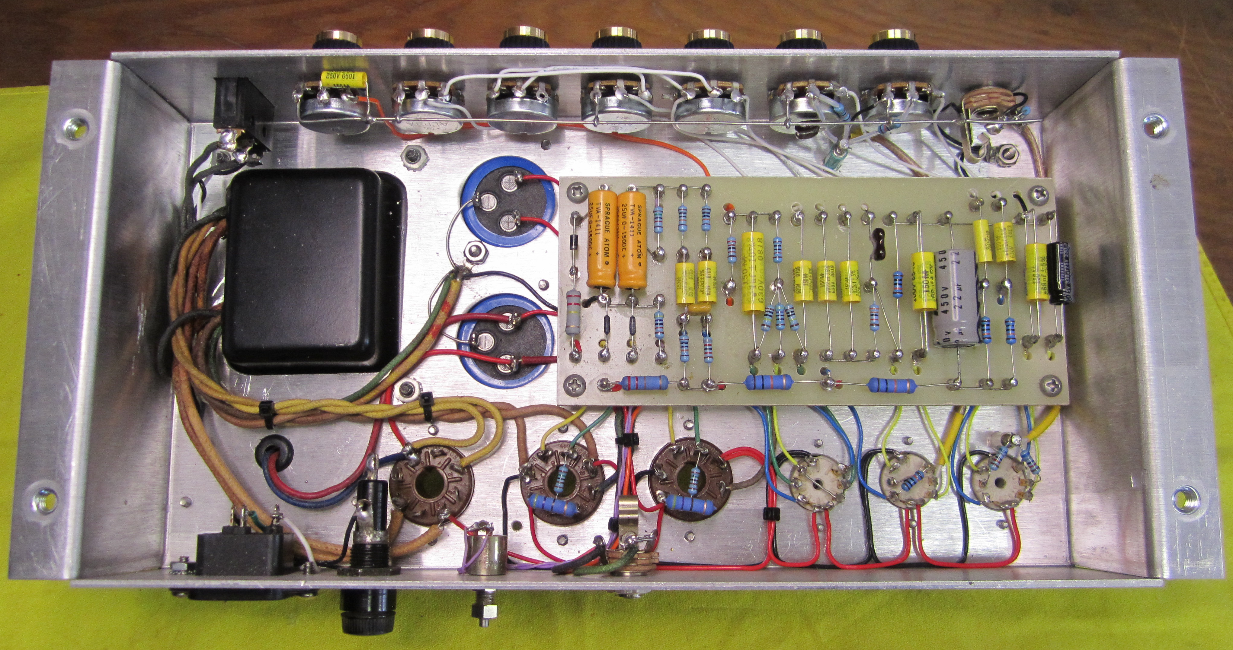
Anyway the build is working now, here's a pic!
EDIT: Audio sample for the interested!
Anyway the build is working now, here's a pic!
EDIT: Audio sample for the interested!
You do not have the required permissions to view the files attached to this post.