Hey all,
How do you (or would you) determine a power resistor value for tube amp testing in the absence of a speaker?
My shoot from the hip assumption is that speaker impedance's are based on a 1K Hz sine wave, and the inductance/resistance reactance gives an opposition of 8 ohms at that frequency.
So, would it be accurate to say that inputting a 1K Hz sine wave with an 8 ohm power resistor would mimic the same load and power transfer as the 8 ohm speaker at 1K Hz?
Thank you!
Best,
Phil
Proper resistive load for speaker output - during testing
Moderators: pompeiisneaks, Colossal
Proper resistive load for speaker output - during testing
I’m only one person (most of the time)

Re: Proper resistive load for speaker output - during testing
It’s an approximation, but a decent one, and that’s how I do my testing.
I build and repair tube amps. http://amps.monkeymatic.com
Re: Proper resistive load for speaker output - during testing
Thanks xtian,
Then I shall fly with that one when its called on for. They threw out a handful of 12 ohm power resistors at work and I found that ser/par combo's of 6 of them can give you 4, 8, 16 and maybe even 2 ohms. Not too shabby.
Best,
Phil D.
Then I shall fly with that one when its called on for. They threw out a handful of 12 ohm power resistors at work and I found that ser/par combo's of 6 of them can give you 4, 8, 16 and maybe even 2 ohms. Not too shabby.
Best,
Phil D.
I’m only one person (most of the time)

Re: Proper resistive load for speaker output - during testing
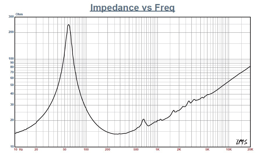
Perform also some test with higher impedances at lower frequencies (see a typical impedance vs frequency plot of a speaker) to have a full idea of how it will work.
Re: Proper resistive load for speaker output - during testing
Thanks Roberto, that sounds like revealing thing to do. Since a speaker is a coil and on the inductive end of things I would imagine that the impedance would increase with higher frequencies and decrease with lower according to some curve.
When I was "deciphering" my output transformer (not any reliable specs to be found on it) I got curious how input/output ratios would change depending on frequencies. From 100 Hz to 1000 Hz it was a fairly flat voltage ratio but then started dropping around 5K Hz or so. By the time I hit 20K Hz the voltage ratio has dropped by around 30% and at 60K Hz it was half the initial Voltage ratio.
That was revealing.
Thank you Roberto, your test suggestion is on my list now.
Best,
Phil
I’m only one person (most of the time)
Re: Proper resistive load for speaker output - during testing
Take a look here:
Re: Proper resistive load for speaker output - during testing
How were you measuring the voltages? If a meter, check it on a scope.pjd3 wrote: ↑Sun May 31, 2020 3:05 pmWhen I was "deciphering" my output transformer (not any reliable specs to be found on it) I got curious how input/output ratios would change depending on frequencies. From 100 Hz to 1000 Hz it was a fairly flat voltage ratio but then started dropping around 5K Hz or so. By the time I hit 20K Hz the voltage ratio has dropped by around 30% and at 60K Hz it was half the initial Voltage ratio.
That was revealing.
https://www.justgiving.com/page/5-in-5-for-charlie This is my step son and his family. He is running 5 marathons in 5 days to support the research into STXBP1, the genetic condition my grandson Charlie has. Please consider supporting him!
Re: Proper resistive load for speaker output - during testing
I use an 8 ohm 200 watt resistor that I purchased on ebay. It gets warm, but works fine for power measurements .
Re: Proper resistive load for speaker output - during testing
Thanks everyone,
My next project will involve more "design" approach from myself since the amp will be for a more unique situation. At minimum I figure I'll need to look at gain stage voltages and power outputs. I wanted to know that at least I was providing a safe reasonable load to the amp output as I determined gain stage amplification throughout the circuit.
And Yeah, I was only using the AC volts setting on a good Fluke True RMS multimeter.
At some point I'll need to bite the bullet and get a good scope. the one I have now is ancient and only showing half screen. I don't even trust using it anymore.
It certainly would be good to see the curves of speakers myself. After all, part of all this isn't just to have fun building good gigging amps (which I just finished the 2nd) but to gather knowledge of all this as we go.
Thank you!
Best, Phil D
I’m only one person (most of the time)
Re: Proper resistive load for speaker output - during testing
If a 200 watt resistor gets warm I may need to spring for something other than what I have, especially that I plan to build my 3rd project with a pair of KT88's. I"m looking for an amp that has alot of clean headroom at moderate stage volumes.
What I can do now is put three paralleled 12 ohm (25 watt) resistors in series with another set of three paralleled 12 ohm resistors to make 8 ohms. I'll just need to take a closer look at the total power rating of that config. I thought it might handle the 20 and 40 watt amps thus far.
Phil D
What I can do now is put three paralleled 12 ohm (25 watt) resistors in series with another set of three paralleled 12 ohm resistors to make 8 ohms. I'll just need to take a closer look at the total power rating of that config. I thought it might handle the 20 and 40 watt amps thus far.
Phil D
I’m only one person (most of the time)
Re: Proper resistive load for speaker output - during testing
Perhaps it may be due to the meter then, eg a discrepancy in the frequency response of different ranges?pdf64 wrote: ↑Mon Jun 01, 2020 9:44 amHow were you measuring the voltages? If a meter, check it on a scope.pjd3 wrote: ↑Sun May 31, 2020 3:05 pmWhen I was "deciphering" my output transformer (not any reliable specs to be found on it) I got curious how input/output ratios would change depending on frequencies. From 100 Hz to 1000 Hz it was a fairly flat voltage ratio but then started dropping around 5K Hz or so. By the time I hit 20K Hz the voltage ratio has dropped by around 30% and at 60K Hz it was half the initial Voltage ratio.
That was revealing.
https://www.justgiving.com/page/5-in-5-for-charlie This is my step son and his family. He is running 5 marathons in 5 days to support the research into STXBP1, the genetic condition my grandson Charlie has. Please consider supporting him!
-
SoulFetish
- Posts: 211
- Joined: Wed Apr 03, 2013 1:50 pm
- Location: Norwood, MA
Re: Proper resistive load for speaker output - during testing
If they are the aluminum, chassis mount resistors, they need to be mounted to a proper heat sink to achieve their stated power rating. But assuming that all other things are good, your total load is rated for 150W (each resistor dissipating 25W a piece).pjd3 wrote: ↑Mon Jun 01, 2020 2:39 pm What I can do now is put three paralleled 12 ohm (25 watt) resistors in series with another set of three paralleled 12 ohm resistors to make 8 ohms. I'll just need to take a closer look at the total power rating of that config. I thought it might handle the 20 and 40 watt amps thus far.
Phil D
Re: Proper resistive load for speaker output - during testing
Yes Soul Fetish they are those kind. Unless there is some heat sink type that is important to use, I was going to look for a healthy block of aluminum or a good size thick steel plate.
And in terms of using the meter to look at V vs Freq, although I haven't yet done the reactance math, wouldn't I expect output to drop as the frequency increases through a coil? I thought that the inductance of a coil as in the primary of a output transformer would as some point act as a low pass filter.
Thanks all!
Best,
Phil
I’m only one person (most of the time)
-
SoulFetish
- Posts: 211
- Joined: Wed Apr 03, 2013 1:50 pm
- Location: Norwood, MA
Re: Proper resistive load for speaker output - during testing
Should be fine. I have load box split into several 50W resistors to spread out the heat and have them mounted to the inside of an extruded aluminum box with a selector to switch between 4Ω, 8Ω, & 16Ω at 300W each, and all of them in parallel for 2Ω (2.285Ω, but who's counting). I anticipate that should be fine, as well as your plan.
Interestingly enough, the primary inductance of a transformer acts as a high pass filter, where the inductance determines the low frequency cutoff.And in terms of using the meter to look at V vs Freq, although I haven't yet done the reactance math, wouldn't I expect output to drop as the frequency increases through a coil? I thought that the inductance of a coil as in the primary of a output transformer would as some point act as a low pass filter.
Thanks all!
Best,
Phil
Yet, high frequencies are affected by the winding capacitance and leakage inductance.
But, like you mentioned - even into a purely resistive load, there is a reactive component which affects the output. Meaning, there is both magnitude and phase. So, one way to beat your head against the wall in a worthwhile endeavor, is to drive just the output with a sine wave and monitor the output in your scopes XY mode.
This is a great, because you can see the phase shifts as you increase and decrease the frequency sweep.
you dig?
This is a great article on amplifier compensation, which is where I learned how to use an oscilloscope XY mode, and interpret lissajous figures. It's written in the context of designing stable negative feedback networks, but has some good general info for this discussion as well. Hope you find it as helpful as I have:
http://www.angelfire.com/electronic/fun ... ation.html
Last edited by SoulFetish on Thu Jun 04, 2020 2:00 am, edited 1 time in total.
Re: Proper resistive load for speaker output - during testing
Thank you ! This is great information. Just looking over this, its obvious that a good understanding of the article in the link you provided will go far in understanding important behaviors in these amps. And something I'll want to know before getting too far in my third project - which I plan to play around a lot with NFB.
Thank you, this will keep me busy for a little while.
Best,
Phil
Thank you, this will keep me busy for a little while.
Best,
Phil
I’m only one person (most of the time)