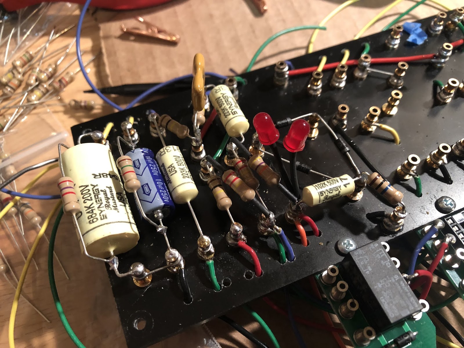
I'm using Synergys, but they're designed by the same guy originally. So I assume this applies to Synergys as well. I wish I would have known this about two hours ago.
The issue of worrying about which end of the cap is attached to the outer foil is a bit overblown, in my opinion.
There are - perhaps - special conditions where this might make a difference. Maybe. However, if you are all about orienting outer foil layers you can get a much better result (in terms of whatever it was you were hoping to get, which is usually foggy) by putting a shield around the outside of the cap and grounding that, ignoring which end is out. A wrap of copper foil tap around the cap, and a wire from that to ground is far more effective than hooking the outer foil to a low impedance point for the purposes usually listed for outer foil applications.
Hmmm. There's a business opportunity - three terminal capacitors. Take an ordinary epoxy-dipped wrapped foil cap; wrap a layer of copper foil around it, with a wire lead coming out; dip it again in pretty-color epoxy, and label it with something like "Hyper-blast Mega-foil!!!" and do a blinding marketing blast about the blatant, yet subtle advantages of three-terminal capacitors.
"It's not what we don't know that gets us in trouble. It's what we know for sure that just ain't so"
Mark Twain
So my options are to rip it all out and correct the positions, likely requiring some component and potential turret replacement. I've never been good at sucking solder out of the inside of a turret, especially when there are other leads that need to be in there still. OR, I could leave it and have a potentially noisy amp. OR, I could shield the cap with an externally grounded shield. Would you be concerned of arcing onto the foil from neighboring turrets?
You know, all of my Marshall-style amps previous to this have been m0j0 kits where the mustard-style caps "can go in either direction". Well, turns out that's bullshit. Why? Because they have some decent hum where other of my amps don't. Go figure. I saw a non-oscilloscope method of using a TS cable that connects +/- leads to clamps that you test caps on an amp's input. Switch the terminals, turn the amp on and grab the cap to see how loud it is. Is this another Mad Mike way of testing caps, or do you need a scope?
I'm glad I read RG's post on the subject. I've tried different ways to determine where the outer foil was on the caps I had available at hand. I could never find a really significant difference.
I have no decent scope, though.
I still manage to find where the outer foil is and orient the caps accordingly, because the multiplication of slight mistakes might cause a significant discrepancy but, I'm still dubious...
1. I spent a lot of time learning how to do this and carefully installed all my caps in builds in the right way, paying attention to where the lowest impedance path was for noise reduction. Then I saw tons of discussions here and on EL34world stating this was massive overkill in a guitar amp. it might very nominally lower noise in a super quiet HiFi build but there is such a near nonexistent change to the hiss with this and the gain of guitar amps is going to swamp any 'noise' this could cause, so I basically stopped and have never noticed. A corollary to this that's been mentioned before.
2. from the mentioned discussion, Marshall, Fender, Vox, Mesa, etc.. likely NEVER deal with this as they have automated processes that randomly grab random capacitors in a random way so that likely about 50% of them are installed 'backwards' and they never have complaints or problems with it being noisy due to this. In fact they likely, due to the randomness often have an amp with 100% capacitors backwards and 100% capacitors the right way. Yet I doubt anyone's ever specifically noticed.
Somewhat of a mixed response, as expected. No problem, of course. Turns out my V1A cathode cap is correct, YAY! The other three, I think, would ideally be reversed. The V1B cathode cap will be easy to reorient. The other two will be an ass pain. We'll see what happens.