
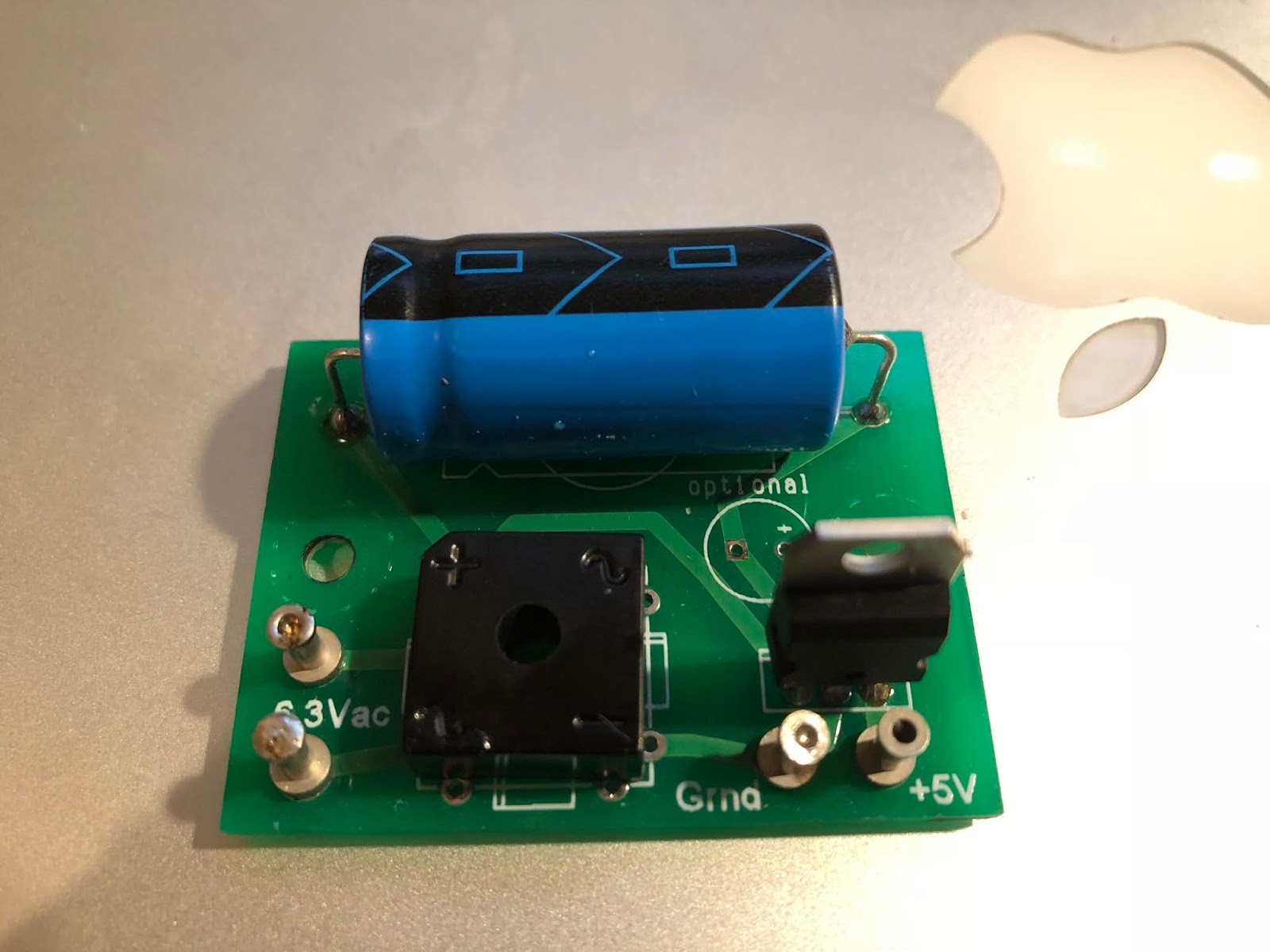
I wired up my PT, fuse, aux 6.3V tranny and Hoffman power supply and got the following:
Hoffman 6.3 V input = 3.7 VAC per side (confirms aux tranny primary and secondary voltages are good)
Hoffman +5V output = -3.37 VDC on the ground terminal and 0.17 VDC on the +5V terminal.
Is this right?
HOFFMAN RELAY SUPPLY VOLTAGES
Moderators: pompeiisneaks, Colossal
HOFFMAN RELAY SUPPLY VOLTAGES
Just plug it in, man.
-
martin manning

- Posts: 14308
- Joined: Sun Jul 06, 2008 12:43 am
- Location: 39°06' N 84°30' W
Re: HOFFMAN RELAY SUPPLY VOLTAGES
My aux 6.3V transformer is center-tapped. I thought that if it wasn't grounded, it would die. Do I need one that's not tapped?
Just plug it in, man.
-
pompeiisneaks

- Site Admin
- Posts: 4244
- Joined: Sat Jan 14, 2017 4:36 pm
- Location: Washington State, USA
- Contact:
Re: HOFFMAN RELAY SUPPLY VOLTAGES
You don't need to use it, and in this case you want the supply for the relays 'floating'
So wrap up the center tap, cut it neat and shrink tube and squish the end so the wire is not able to ground out inside the chassis. Then use two 100ohm resistors to ground on either side of the heaters to create a virtual center tap on the heater line somewhere.
Edit: clarity... didn't make sense, hopefully does now.
~Phil
tUber Nerd!
Re: HOFFMAN RELAY SUPPLY VOLTAGES
I see on Hoffman's site that he diagrams a non-CT 6.3 V heater supply with the artificial center tap you described like this:pompeiisneaks wrote: ↑Wed Apr 22, 2020 10:10 pm You don't need to use it, and in this case you want the supply for the relays 'floating'
So wrap up the center tap, cut it neat and shrink tube and squish the end so the wire is not able to ground out inside the chassis. Then use two 100ohm resistors to ground on either side of the heaters to create a virtual center tap on the heater line somewhere.
Edit: clarity... didn't make sense, hopefully does now.
~Phil

What I don't understand is if 6.3 V is making it to the 6.3 V relay supply input, what difference would a artificial center tap make? Do I just run a 100R resistor from each 6.3V turret to ground?
Just plug it in, man.
Re: HOFFMAN RELAY SUPPLY VOLTAGES
That Hoffman drawing assumes you will be using the filament winding on your PT. But you are using a separate 6.3 transformer. So, don't use any 100Ω resistors for a center tap. They will do nothing for your power supply. Also, it's fine to connect the negative side of the bridge and filter cap to chassis ground.What I don't understand is if 6.3 V is making it to the 6.3 V relay supply input, what difference would a artificial center tap make? Do I just run a 100R resistor from each 6.3V turret to ground?
If you are using Hoffman's regulator board you should measure 5v at the output.
-
martin manning
- Posts: 14308
- Joined: Sun Jul 06, 2008 12:43 am
- Location: 39°06' N 84°30' W
Re: HOFFMAN RELAY SUPPLY VOLTAGES
You are using an auxiliary transformer, no? If so I wouldn't bother with the 2x 100Ω, as there is no need to center the AC voltage. Just ground the bridge rectifier and the DC voltage as shown in the Hoffman diagram. If I were going to power the relays from the filament supply winding, I would ground the transformer CT or use the 2x 100Ω, and isolate the DC voltage from ground.
Re: HOFFMAN RELAY SUPPLY VOLTAGES
Thanks, man. So I can see on the board that connecting the "ground" turret to chassis ground will obviously accomplish this.sluckey wrote: ↑Wed Apr 22, 2020 11:31 pmThat Hoffman drawing assumes you will be using the filament winding on your PT. But you are using a separate 6.3 transformer. So, don't use any 100Ω resistors for a center tap. They will do nothing for your power supply. Also, it's fine to connect the negative side of the bridge and filter cap to chassis ground.What I don't understand is if 6.3 V is making it to the 6.3 V relay supply input, what difference would a artificial center tap make? Do I just run a 100R resistor from each 6.3V turret to ground?
If you are using Hoffman's regulator board you should measure 5v at the output.
I would also run wires from these two turrets out to my relay coils, yes? If I ground the Hoffman supply "ground" turret and my aux transformer is center-tapped, does this create a ground loop?
Thanks as always.
Just plug it in, man.
Re: HOFFMAN RELAY SUPPLY VOLTAGES
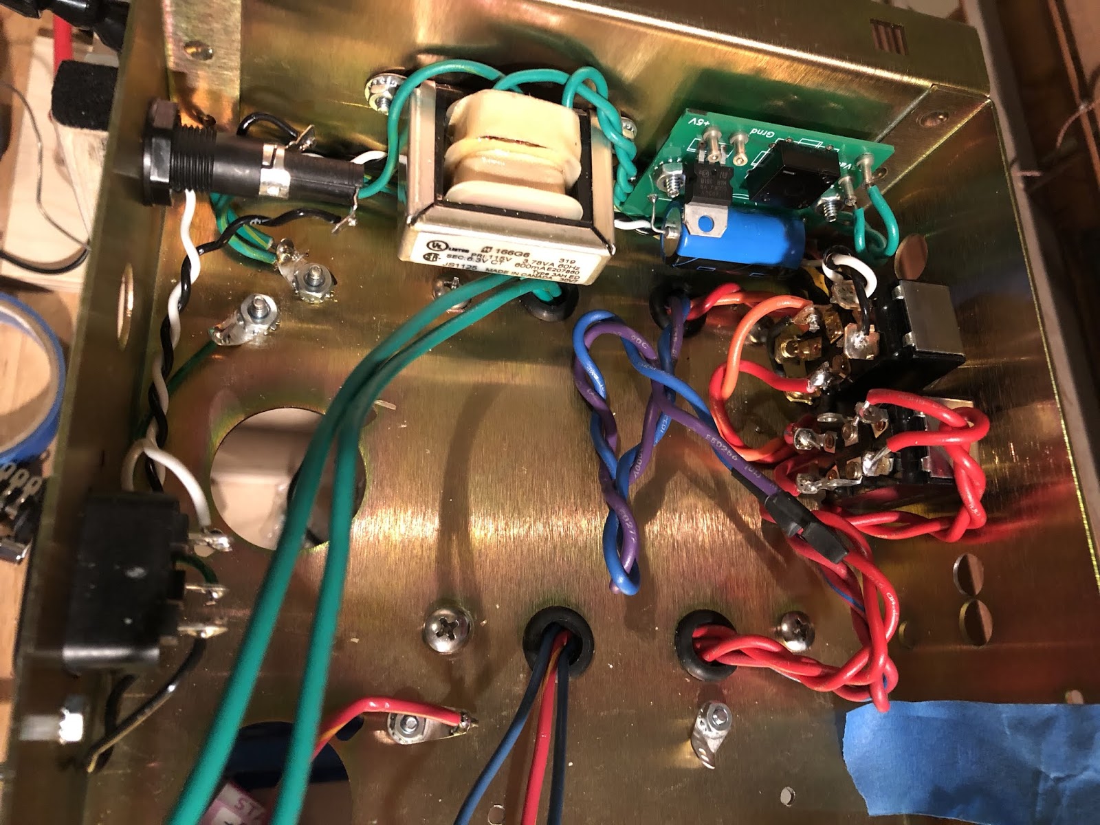
The Hoffman Power Supply board has a direct PCB route from the filter cap "-" through the regulator ground to the ground turret. I grounded the turret like so:
Now I get 2.2 VAC and 2.0 VAC on the 6.3V board input, no voltage on the ground connection and still about 0.10 VDC on the +5 VDC output. This has been the same on two Hoffman boards I've tried so far. WTF? Is grounding the aux tranny center tap verboten?
Now I get 2.2 VAC and 2.0 VAC on the 6.3V board input, no voltage on the ground connection and still about 0.10 VDC on the +5 VDC output. This has been the same on two Hoffman boards I've tried so far. WTF? Is grounding the aux tranny center tap verboten?
Just plug it in, man.
-
martin manning
- Posts: 14308
- Joined: Sun Jul 06, 2008 12:43 am
- Location: 39°06' N 84°30' W
Re: HOFFMAN RELAY SUPPLY VOLTAGES
Do not ground the CT! You are actually shorting half of the transformer secondary each half cycle through the diodes in the bridge.
Re: HOFFMAN RELAY SUPPLY VOLTAGES
DISCONNECT THAT CT!This has been the same on two Hoffman boards I've tried so far. WTF? Is grounding the aux tranny center tap verboten?
The FWB on both boards is most likely damaged and needs to be replaced. If you are lucky the PT is still OK.
Re: HOFFMAN RELAY SUPPLY VOLTAGES
LOL, I can just see you guys-- "WTF?????"
OK, problem solved! The aux tranny CT spec was a bad call by yours truly. I cut and double insulated it. Now the relay supply reads 4.97 VDC on the +5V output, and there are proper voltages on the power supply input (although a couple tenths of a volt hotter) and the PT primary and secondary readings are perfect.
Replacing the FWB is easy, I might just do that to play it safe.
THANK YOU, GUYS!
Just plug it in, man.
Re: HOFFMAN RELAY SUPPLY VOLTAGES
You lucky dude! May want to check that other power supply too.
Re: HOFFMAN RELAY SUPPLY VOLTAGES
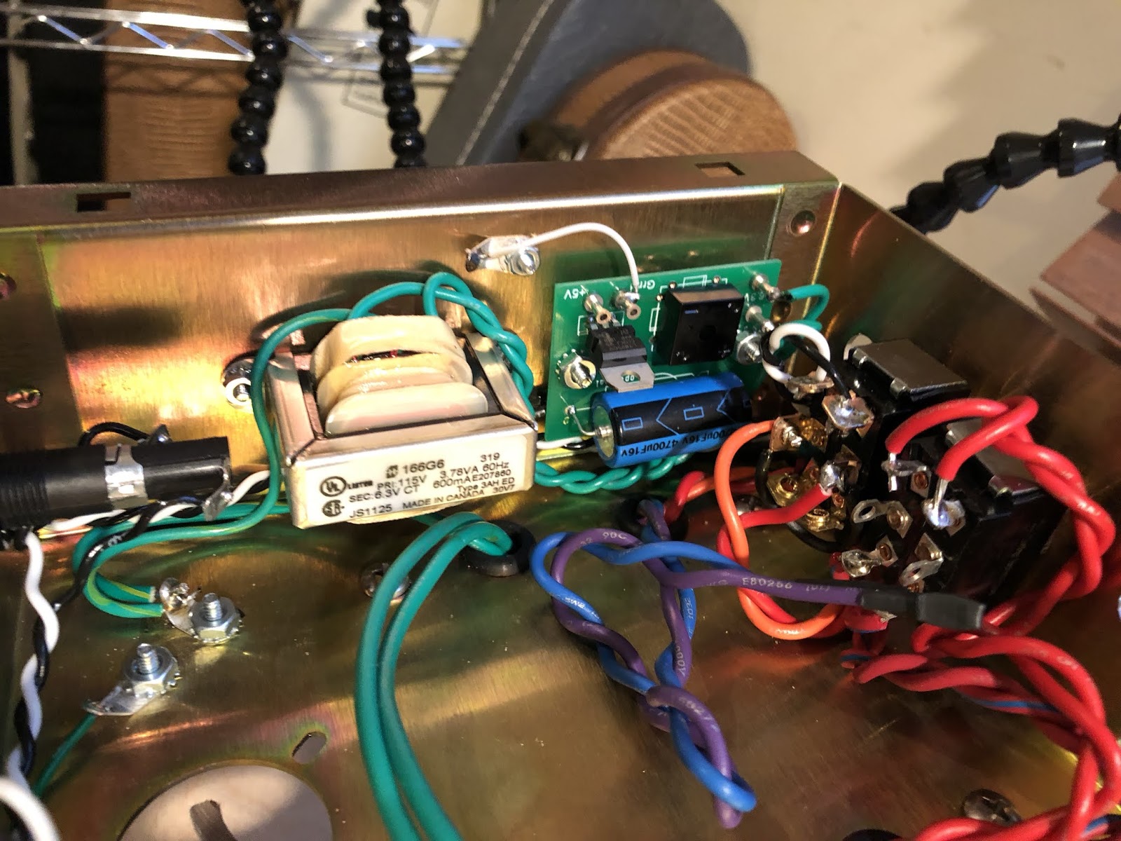
Let's hope so. Thanks, man. Here's what it looks like for the moment:
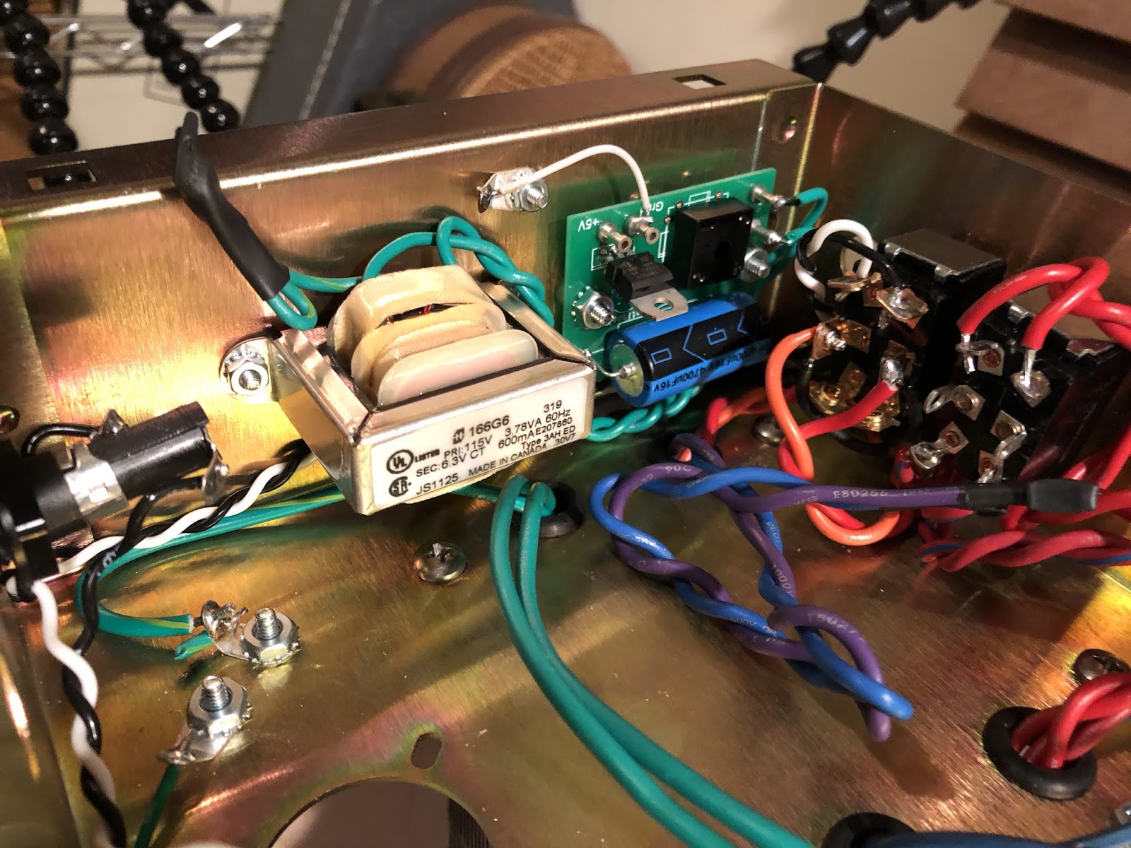
Since I cut and shrunk the CT, the aux transformer output increased to 3.8 and 4.0 VAC per side. Since I have 4.97 VDC on the supply output, the relays won't know the difference. RRRRRRRIGHT? Or will an extra volt bake the rectifier/regulator?
Since I cut and shrunk the CT, the aux transformer output increased to 3.8 and 4.0 VAC per side. Since I have 4.97 VDC on the supply output, the relays won't know the difference. RRRRRRRIGHT? Or will an extra volt bake the rectifier/regulator?
Just plug it in, man.
Re: HOFFMAN RELAY SUPPLY VOLTAGES
I diode-tested each diode on the installed FWB with my DMM and came up with "0.56 V" per side. The first one I installed reads "0.59 V" per side.
Just plug it in, man.