Yes I've used the hoffman boards many times and they work great.
~Phil
RELAY POWER SUPPLY
Moderators: pompeiisneaks, Colossal
-
pompeiisneaks

- Site Admin
- Posts: 4244
- Joined: Sat Jan 14, 2017 4:36 pm
- Location: Washington State, USA
- Contact:
1 others liked this
Re: RELAY POWER SUPPLY
tUber Nerd!
-
SoulFetish
- Posts: 211
- Joined: Wed Apr 03, 2013 1:50 pm
- Location: Norwood, MA
Re: RELAY POWER SUPPLY
Again, I would just caution you to install an overvoltage/fuse circuit to protect your down-stream devices. It's not uncommon for the HT to short to the heater supply via internal tube short (most common), or drink/liquid spillage inside the amp (as was the case in the AC15C1 I had on the bench today).
-
SoulFetish
- Posts: 211
- Joined: Wed Apr 03, 2013 1:50 pm
- Location: Norwood, MA
1 others liked this
Re: RELAY POWER SUPPLY
something like this:
You do not have the required permissions to view the files attached to this post.

Re: RELAY POWER SUPPLY
Please forgive this [noob] question:
When the relay connection is described as "normally closed", is that a normal in the absence of voltage, or the presence of voltage? I understand that the relay switches when you change it, or when the hot shorts to ground. But is the circuit not normal when it's turned on? Forgive me if I'm trespassing into the rhetorical for most of you, but I can't find this answer and it's making my brain hurt. Thanks.
When the relay connection is described as "normally closed", is that a normal in the absence of voltage, or the presence of voltage? I understand that the relay switches when you change it, or when the hot shorts to ground. But is the circuit not normal when it's turned on? Forgive me if I'm trespassing into the rhetorical for most of you, but I can't find this answer and it's making my brain hurt. Thanks.
Last edited by ViperDoc on Mon Mar 23, 2020 3:26 am, edited 1 time in total.
Just plug it in, man.

Re: RELAY POWER SUPPLY
HAHAHAHAHA!!!! INDEED!!!!
Not sure what happened there, I was going for "noob". Corrected!
Not sure what happened there, I was going for "noob". Corrected!
Just plug it in, man.
Re: RELAY POWER SUPPLY
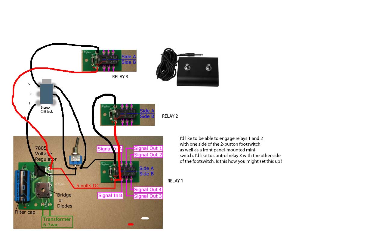
I'd like to control 2 relays with one side of a 2-button footswitch and also control the same with a front-panel mounted mini switch, and control a 3rd relay with the other side of the footswitch. Is this how you might set this up? I had to use a paint program in a pinch, so please forgive the sloppy drawing. Thanks for looking.
Just plug it in, man.
Re: RELAY POWER SUPPLY
The switch on the front panel, and the switch in your foot switch, perform the same function in this circuit: shorting the hot and ground together across the diode. If you have both a foot switch and front panel switch, if either one is in the 'shorted' position, then the relay will react as a 'shorted' position. I normally either use a on-off-on switch on the front panel, with the middle position marked 'footswitch', or use an on-on switch with the open side marked footswitch. That ensures that the front panel is in the open (non-shorted) position so the footswitch can work properly. If you accidentally have the front panel switch in the 'shorted' position, the footswitch won't do anything.
In your diagram, the black wire needs to go to the middle post of your switch, the red wire to one of the other positions. Then it would be open (no short) in one position, closed (short) in the other. You can test this by touching the red and black wires together briefly. You will hear the relay latches triggering.
I generally put my clean channel in the default postion (i.e. state it's in when no power is applied to amp), crunch in the other. But it works either way.
Re: RELAY POWER SUPPLY
You’ll likely recognize the graphics I used from the Hoffman amps website. His mini switch disconnects the ground (black) wire, which gets back to my original question before my typing skills went to pot: does powering the relay make it “normal” or not? I tried to design the footswitch the same way as the mini switch so that both would work the same way. You are right, the mini switch has to be open for the footswitch to work, I’m fine with that. I suppose you can operate the relay by either disconnecting the ground or shorting ground and hot together. Correct or no?
If I want an LED to light on the footpedal when I kick it, I’m going to need to wire the hot and ground to the jack, is this right? Thanks.
If I want an LED to light on the footpedal when I kick it, I’m going to need to wire the hot and ground to the jack, is this right? Thanks.
Just plug it in, man.
-
sluckey
- Posts: 3528
- Joined: Sun Jul 22, 2007 7:48 pm
- Location: Mobile, AL
- Contact:
1 others liked this
Re: RELAY POWER SUPPLY
Here's a dual 3-way footswitch to add to the confusion. 
You do not have the required permissions to view the files attached to this post.
-
sluckey
- Posts: 3528
- Joined: Sun Jul 22, 2007 7:48 pm
- Location: Mobile, AL
- Contact:
1 others liked this
Re: RELAY POWER SUPPLY
Let's talk about relay terminology.
A relay coil is said to be de-energized when no power is applied. A relay coil is said to be energized when power is applied.
Relay contacts usually have a standard terminology associated with them.
C = Common... This is the movable contact.
NC = Normally Closed... This contact is connected to the Common contact when the relay coil is de-energized.
NO = Normally Open... This contact is ***NOT*** connected to the Common contact when the relay coil is de-energized.
When you energize the coil, the Common contact moves and will now be connected to the Normally Open contact and will no longer be connected to the Normally Closed contact.
Learning and understanding this terminology will make working with relays very easy.
Oh yeah, you will never be shorting the hot and ground together!
Re: RELAY POWER SUPPLY
OK, THAT’S WHAT I’M TALKING ABOUT! Nice. THANK YOU!
So the relay is normal until you charge the coil (connect + and - to their respective terminals). I’m still unsure how to properly wire a simple 2-button switch jack and allow a led to turn on inside the pedal and in the front panel.
So the relay is normal until you charge the coil (connect + and - to their respective terminals). I’m still unsure how to properly wire a simple 2-button switch jack and allow a led to turn on inside the pedal and in the front panel.
Just plug it in, man.
Re: RELAY POWER SUPPLY

This is the schematic on the Hoffman website. Would you then put the + onto the common/sleeve connection? The jack itself needs to NOT be chassis-grounded for relay purposes. Thanks all.
Just plug it in, man.
-
sluckey
- Posts: 3528
- Joined: Sun Jul 22, 2007 7:48 pm
- Location: Mobile, AL
- Contact:
1 others liked this
Re: RELAY POWER SUPPLY
QUIT SAYING THAT! A relay is ALWAYS normal. With no voltage applied the relay is DE-ENERGIZED. When you apply voltage the relay becomes ENERGIZED. Either state is quite normal.
The easiest thing for you to do is put a 9 volt battery in the footswitch body. Now use a DPST footswitch. One pole will switch your relay circuit. The other pole will connect the battery through a 1K resistor to the LED. Easy peasy.I’m still unsure how to properly wire a simple 2-button switch jack and allow a led to turn on inside the pedal and in the front panel.
As for the LED on the front panel... Connect a 470Ω current limiting resistor in series with the LED. Now connect this series pair directly across the relay coil (observe polarity). Easy peasy.
With this simple arrangement you can now use a two circuit phone jack (often called stereo jack). ISOLATE THE SLEEVE FROM CHASSIS. May I suggest to use the 6 lug Cliff jack. Now all you need is a 3 conductor cable. This will allow you to operate two separate relays like you mentioned earlier.