Bias trimpots maxed out. Change trimpots or resistor?
Moderators: pompeiisneaks, Colossal
Bias trimpots maxed out. Change trimpots or resistor?
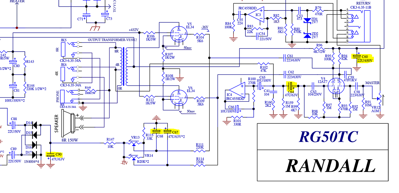
Greetings! I have a Randall RH50T I recently acquired and was doing a bit of a check up on it. It currently has 6AC7 tubes in it with about 450v at the plates. The lowest I can get adjusting the trimpots is about 41ma on one tube and 39ma on the other.I am trying to get them down to about 35ma. The trim pots are B20k. Looking at the circuit to me it looks like I have two options for getting more range. One to change the trimpots to B25k or 33k. The other is possibly changing R147, which is right after the trimpots and before the rectifing diodes, to maybe 15k or 20k. It is currently 10k. Does this sound correct? Thanks!
-
thetragichero
- Posts: 478
- Joined: Tue Sep 10, 2019 7:46 pm
Re: Bias trimpots maxed out. Change trimpots or resistor?
most of my tinkering experience is with cathode bias so wait until somebody else confirms but:
if we're looking for more negative voltage, wouldn't we want to decrease the dropping resistor instead of increase it?
am I picturing this wrong in my head?
if we're looking for more negative voltage, wouldn't we want to decrease the dropping resistor instead of increase it?
am I picturing this wrong in my head?
PRR wrote: Plotting loadlines is only for the truly desperate, or terminally bored.

Re: Bias trimpots maxed out. Change trimpots or resistor?
You need to increase the value of R115. R115 is dumping some of your bias voltage to ground. The larger you make R115, the more negative bias voltage you can generate, and this will allow you to set the tubes cooler. Try a 47K in there.
I build and repair tube amps. http://amps.monkeymatic.com
Re: Bias trimpots maxed out. Change trimpots or resistor?
Decrease R147 or increase R115. Much cheaper and easier than replacing pots.
-
thetragichero
- Posts: 478
- Joined: Tue Sep 10, 2019 7:46 pm
Re: Bias trimpots maxed out. Change trimpots or resistor?
non-destructive way of temporarily decreasing r147 would be to solder an appropriately-sized resistor in parallel to it (47k would give you approximately 8k2, 22k approximately 6k8, etc)
i think increasing r115 would be the way to go because i like conservation
i think increasing r115 would be the way to go because i like conservation
PRR wrote: Plotting loadlines is only for the truly desperate, or terminally bored.
Re: Bias trimpots maxed out. Change trimpots or resistor?
Thank you gentlemen for the responses! I didn't even think about R115. Not to mention for some reason I though I need to add resistance at the trimpots or after. I do appreciate the feedback.

Re: Bias trimpots maxed out. Change trimpots or resistor?
I always prefer not to decrease loads on supply circuits, because it means more stress to the upstream parts of the circuit. In this case you have around -80 Vdc and around 50k load, so the stress for the winding it’s just charge the caps at the beginning.
R115 to 39k or 47k would do the job. Being in a rush I would solder a resistor in parallel to R147.
One personal note: why connecting the caps to the wipers of the pots, that can loose contact and cause issues, instead of connecting thembetween R115 and the bottom part of the pots? IMHO would be better.