CHANGES NEEDED TO RUN KT66 IN A JTM45 KIT AMP?

General discussion area for tube amps.

Moderators: pompeiisneaks, Colossal

Post Reply
User avatar
ViperDoc
Posts: 1247
Joined: Tue Dec 24, 2019 2:21 am
Location: Idaho

CHANGES NEEDED TO RUN KT66 IN A JTM45 KIT AMP?

Post by ViperDoc »

All right, so I'm going to build a JTM45 from a Mojotone British JTM45 mod 3 kit next. (Right after I purchased it, Mojo "upgraded to mod 4" which has a 50k bias pot built in along with some grounding and other changes. Thank you! ) The mod 3 kit schematic makes a bias resistor value change recommendation when running KT66 vs. the stock EL34s. I think I want to have a fixed-adjustable bias design, however, and would like to use a CTS 50KL pot in series with another resistor or your standard bias pot--whatever is best.

FULL DISCLOSURE: Last time I tried following guidance on the internet to do this, it didn't work how I planned. How do I wire the pot in to allow for adjustable bias?

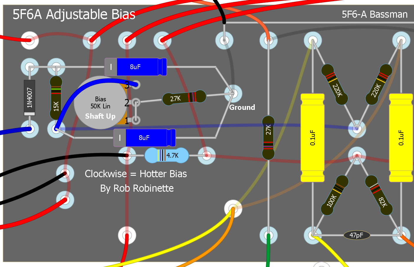
Here is the mod 3 wiring diagram (my kit):

Image

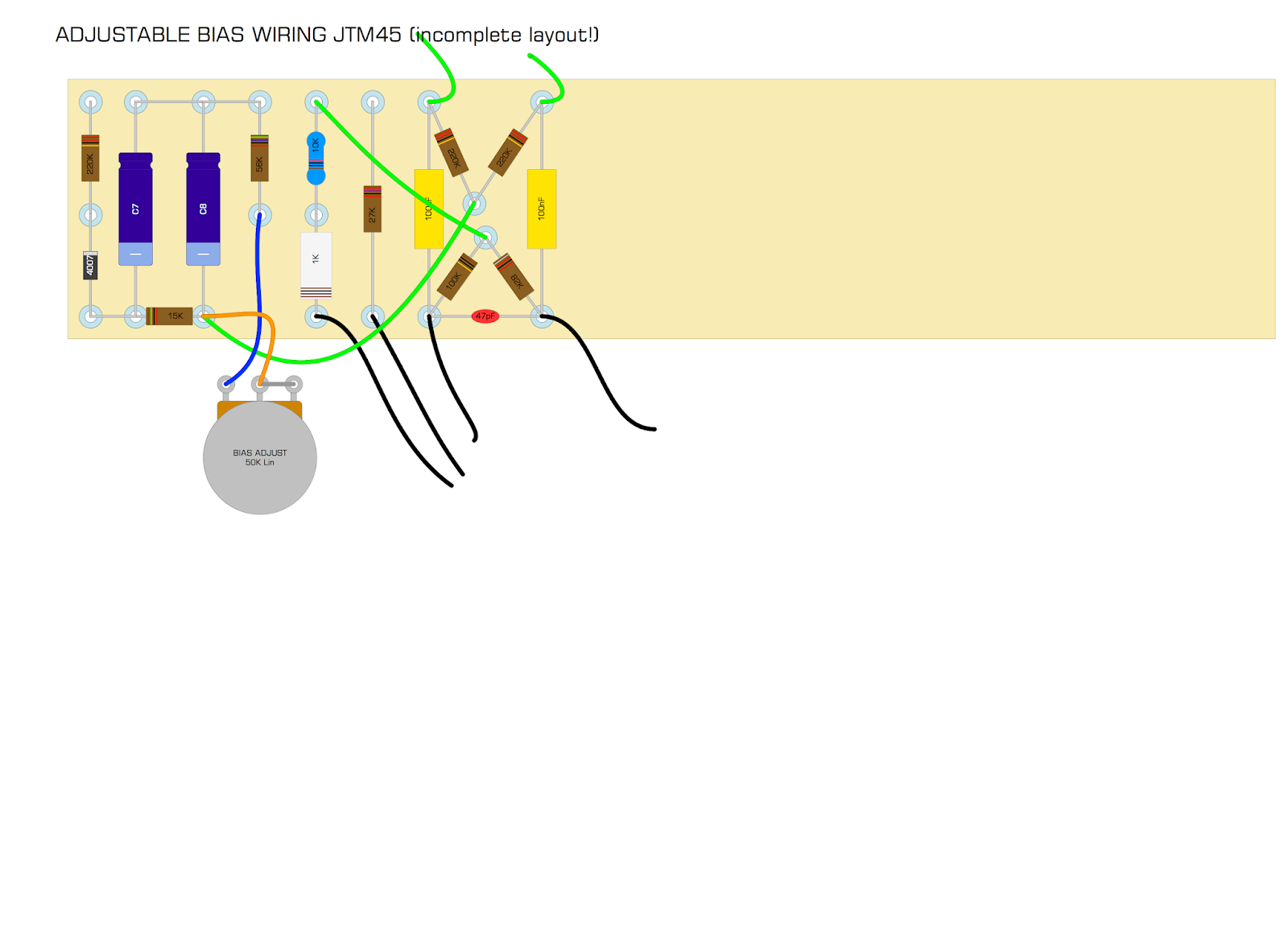
Here's the mod 4 wiring diagram:

Image

The mod 4 bias wire heads into the bias pot's center lug and appears to be attached on one side to the standard 56K resistor, and completely unattached on the other. I've seen adjustable bias pots where the other side is wired to the bias divider (like the mod 3 diagram), which is the way I "believe" I wired my previous attempt. In that setup, the un-trimmed bias was low to begin with, and when I turned the bias pot "up", the bias current got even lower. I used a TAD Bias Master to do all the measuring. If I do it the mod 4 way and choose a 56K resistor connected to the pot, is that enough bias to run KT66? I imagine that's why this version is setup that way, but I'm still a nooblet. That's why I'm asking. Which way is better?

What else would you consider when running KT66 in a JTM45?

THANK YOU!
Just plug it in, man.
User avatar
drew
Posts: 731
Joined: Wed Jun 21, 2006 2:49 am

Re: CHANGES NEEDED TO RUN KT66 IN A JTM45 KIT AMP?

Post by drew »

The bias pot wiring on Rev 5 of the schematic (look on the mojotone site; I can’t figure out how to copy/paste it on the iPad) doesn’t match how it’s drawn in the Rev 4 layout.
User avatar
ViperDoc
Posts: 1247
Joined: Tue Dec 24, 2019 2:21 am
Location: Idaho

Re: CHANGES NEEDED TO RUN KT66 IN A JTM45 KIT AMP?

Post by ViperDoc »

drew wrote: Tue Jan 07, 2020 6:48 am The bias pot wiring on Rev 5 of the schematic (look on the mojotone site; I can’t figure out how to copy/paste it on the iPad) doesn’t match how it’s drawn in the Rev 4 layout.
I see what you mean. The schematic connects to the bias divider but the diagram doesn’t. This is exactly my question!
Just plug it in, man.
sluckey
Posts: 3528
Joined: Sun Jul 22, 2007 7:48 pm
Location: Mobile, AL
Contact:

Re: CHANGES NEEDED TO RUN KT66 IN A JTM45 KIT AMP?

Post by sluckey »

Looking at the layout rev. 4... one end of the pot connects to the 56K, the wiper connects to the 15K, and the other end connects to nothing. This is preferred over the schematic rev. 5 wiring. (I would connect the unused end to the wiper.)

To change between EL34s and KT66s the only change would be the 220K before the diode. But that may not be necessary. I'd just build as shown, fire it up with no tubes and check the negative voltage range on pin 5 of the output tubes while turning the pot end to end. Just may be OK as is. If not, diddle the value of that 220K. If you need more negative voltage, decrease the value of the resistor.
User avatar
ViperDoc
Posts: 1247
Joined: Tue Dec 24, 2019 2:21 am
Location: Idaho

Re: CHANGES NEEDED TO RUN KT66 IN A JTM45 KIT AMP?

Post by ViperDoc »

I asked Mojo and they corrected the schematic like this:

Image

So the lug IS left unconnected, right?
Just plug it in, man.
User avatar
ViperDoc
Posts: 1247
Joined: Tue Dec 24, 2019 2:21 am
Location: Idaho

Re: CHANGES NEEDED TO RUN KT66 IN A JTM45 KIT AMP?

Post by ViperDoc »

sluckey wrote: Tue Jan 07, 2020 5:58 pm Looking at the layout rev. 4... one end of the pot connects to the 56K, the wiper connects to the 15K, and the other end connects to nothing. This is preferred over the schematic rev. 5 wiring. (I would connect the unused end to the wiper.)

To change between EL34s and KT66s the only change would be the 220K before the diode. But that may not be necessary. I'd just build as shown, fire it up with no tubes and check the negative voltage range on pin 5 of the output tubes while turning the pot end to end. Just may be OK as is. If not, diddle the value of that 220K. If you need more negative voltage, decrease the value of the resistor.
Thanks, Sluckey. Take a look at this example of a bias pot by Rob Robinette on his Bassman:

Image

The bias wire goes into the end of the pot and connects the wiper and the other lug to the outgoing series resistor. The Mojo mod 4 bias pot comes into the wiper. If you connect the wiper and the unused lug on the pot and go out of the other lug, is that the same?
Just plug it in, man.
thetragichero
Posts: 478
Joined: Tue Sep 10, 2019 7:46 pm

Re: CHANGES NEEDED TO RUN KT66 IN A JTM45 KIT AMP?

Post by thetragichero »

sluckey wrote: Tue Jan 07, 2020 5:58 pm Looking at the layout rev. 4... one end of the pot connects to the 56K, the wiper connects to the 15K, and the other end connects to nothing. This is preferred over the schematic rev. 5 wiring. (I would connect the unused end to the wiper.)

To change between EL34s and KT66s the only change would be the 220K before the diode. But that may not be necessary. I'd just build as shown, fire it up with no tubes and check the negative voltage range on pin 5 of the output tubes while turning the pot end to end. Just may be OK as is. If not, diddle the value of that 220K. If you need more negative voltage, decrease the value of the resistor.
+1 to always connect the unused lug. it's there and every bit of more reliable/safe is worth it

if you need more out of the bias adjustment than the 220k resistor will give you, instead of desoldering potentially several times look into tacking a parallel resistor to the 220k. play with a parallel resistor calculator (or do the math by hand, whatever floats your boat to see what the resulting value will be
there's not really much to add besides what has already been covered
PRR wrote: Plotting loadlines is only for the truly desperate, or terminally bored.
User avatar
ViperDoc
Posts: 1247
Joined: Tue Dec 24, 2019 2:21 am
Location: Idaho

Re: CHANGES NEEDED TO RUN KT66 IN A JTM45 KIT AMP?

Post by ViperDoc »

thetragichero wrote: Tue Jan 07, 2020 8:02 pm
sluckey wrote: Tue Jan 07, 2020 5:58 pm Looking at the layout rev. 4... one end of the pot connects to the 56K, the wiper connects to the 15K, and the other end connects to nothing. This is preferred over the schematic rev. 5 wiring. (I would connect the unused end to the wiper.)

To change between EL34s and KT66s the only change would be the 220K before the diode. But that may not be necessary. I'd just build as shown, fire it up with no tubes and check the negative voltage range on pin 5 of the output tubes while turning the pot end to end. Just may be OK as is. If not, diddle the value of that 220K. If you need more negative voltage, decrease the value of the resistor.
+1 to always connect the unused lug. it's there and every bit of more reliable/safe is worth it

if you need more out of the bias adjustment than the 220k resistor will give you, instead of desoldering potentially several times look into tacking a parallel resistor to the 220k. play with a parallel resistor calculator (or do the math by hand, whatever floats your boat to see what the resulting value will be
there's not really much to add besides what has already been covered
Thanks, Hero!
Just plug it in, man.
User avatar
ViperDoc
Posts: 1247
Joined: Tue Dec 24, 2019 2:21 am
Location: Idaho

Re: CHANGES NEEDED TO RUN KT66 IN A JTM45 KIT AMP?

Post by ViperDoc »

I've drawn a sketch of how I might add a 50KL bias pot to the mod 3 version of the drawing. I didn't want to redraw the whole diagram, so I know there are wires missing. Please forgive. I'm just focusing what you all suggested into the following DIYLC working sketch:

Image

TWO QUESTIONS:

1) Does this look right to you? It does to me.

2) If I was to design a circuit with INDIVIDUAL BIAS POTS FOR EACH OUTPUT TUBE, what would that look like AND is it worth doing?

THANK YOU!
Just plug it in, man.
Post Reply