Interesting Michailoff Amp from ~1979
Moderators: pompeiisneaks, Colossal
-
turbofeedus
- Posts: 205
- Joined: Wed Jan 30, 2019 5:37 am
Interesting Michailoff Amp from ~1979
Photo album
Bee3 guitar show was this weekend, so I took the drive over to Oaks, PA. Guy was just standing by the door with this interesting looking amp, so I had to see what's up.
He wanted peanuts for it, so I made it mine.
Turns out to be an amp made by a tech out of Allentown, PA named Alex Michailoff. Seems like there's a couple of his amps floating around. Unfortunately he passed in 2008. RIP.
The seller was actually a woodworker and built the cabinet. Nice looking dovetail jointed walnut cab with an oil finish. Beautiful, but man the amp was already heavy enough!
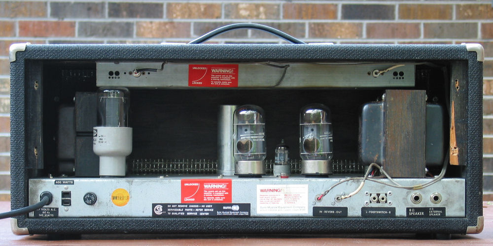
2x6550, 5x12AX7. Big ol' transformers from Saratoga Industries (Espey, EIA 174) out of NY.
I believe the pots are all AB, money was definitely put into the components.
Work inside is clean, a bit more spagetti-ey than I like, but there was definitely a lot of love in this build.
I drew up a schematic, first time using JSchem so apologies for any trouble reading;
Two DC coupled cathode follower stages, cathodyne PI, fender reverb, PP 6550 output. There are taps on the OT for the screens, but they're not being used.
Interested to hear what yall think. I have some work to do on the chassis, and, without firing it up, I assume the electrolytics need to go.
You do not have the required permissions to view the files attached to this post.
Re: Interesting Michailoff Amp from ~1979
cool amp !
Interesting with two DC coupled cathode follower stages
Interesting with two DC coupled cathode follower stages
-
turbofeedus
- Posts: 205
- Joined: Wed Jan 30, 2019 5:37 am
Re: Interesting Michailoff Amp from ~1979
Looking from the rear I see a lot of Sunn inspiration.
http://sluckeyamps.com/sunn/sunn_02.jpg
That bias supply is very dangerous!
http://sluckeyamps.com/sunn/sunn_02.jpg
That bias supply is very dangerous!
-
turbofeedus
- Posts: 205
- Joined: Wed Jan 30, 2019 5:37 am
Re: Interesting Michailoff Amp from ~1979
Agreed, and it has potential to be one in circuit too with this OT.sluckey wrote: ↑Tue Jul 16, 2019 3:03 pm Looking from the rear I see a lot of Sunn inspiration.
http://sluckeyamps.com/sunn/sunn_02.jpg
Dangerous as in I must have made a mistake in my schematic? Or dangerous as in bad design?
Re: Interesting Michailoff Amp from ~1979
You can adjust the bias pot to ZERO volts at point F! One end of the pot is really connected to chassis. Those 6550s will probably never need a bias voltage less than about -40v. I suggest a resistor between the pot and ground that will limit the lower adjust range to about -40v.
While messing around with it you may consider adding a high value "failsafe" resistor between the wiper and the left side of the pot. Without this resistor if the pot wiper opens the bias voltage goes to zero. The failsafe resistor insures the bias voltage will still get to the tubes if the wiper fails.
Zero volts bias will damage/destroy those 6550s very quickly.
-
turbofeedus
- Posts: 205
- Joined: Wed Jan 30, 2019 5:37 am
Re: Interesting Michailoff Amp from ~1979
Ah I see it now, yeah yikes. I also don’t see the purpose of the 100K to ground before the diode? Merlin shows something similar, but only when it’s used to charge a coupling cap. Seems like it could be omitted, or repurposed for the failsafe resistor at least.sluckey wrote: ↑Tue Jul 16, 2019 4:20 pm You can adjust the bias pot to ZERO volts at point F! One end of the pot is really connected to chassis. Those 6550s will probably never need a bias voltage less than about -40v. I suggest a resistor between the pot and ground that will limit the lower adjust range to about -40v.
While messing around with it you may consider adding a high value "failsafe" resistor between the wiper and the left side of the pot. Without this resistor if the pot wiper opens the bias voltage goes to zero. The failsafe resistor insures the bias voltage will still get to the tubes if the wiper fails.
Zero volts bias will damage/destroy those 6550s very quickly.
Re: Interesting Michailoff Amp from ~1979
He chose to divide the HT AC voltage down to a usable value rather than divide the negative dc voltage like you usually see. I would remove that 100K and put it between the right side of the pot and ground. Then pull the 6550s and monitor the negative voltage on pin 5 of the 6550 sockets. Turn the bias pot to one extreme and record the voltage on pin 5. Now turn the bias pot to the other extreme and record the voltage. What do you have?I also don’t see the purpose of the 100K to ground before the diode?
You need something like a 2.2M for the safety resistor.
-
turbofeedus
- Posts: 205
- Joined: Wed Jan 30, 2019 5:37 am
Re: Interesting Michailoff Amp from ~1979
Ah, right, voltage divider. Duh. It's funny how not seeing things drawn as you have before messes with your brain. And I was the one that drew it!
I'll get back to you on this. I'm in between a bunch of projects and will be coming back to this.sluckey wrote: ↑Tue Jul 16, 2019 6:28 pm I would remove that 100K and put it between the right side of the pot and ground. Then pull the 6550s and monitor the negative voltage on pin 5 of the 6550 sockets. Turn the bias pot to one extreme and record the voltage on pin 5. Now turn the bias pot to the other extreme and record the voltage. What do you have?
I was thinking 100K only because that's the value Merlin uses. Should it always be 2.2M, or maybe it changes based on the pot and shunt resistor value?
Re: Interesting Michailoff Amp from ~1979
2.2M is very often seen on PPIMV pots. Should be fine for the bias pot as well. This value is large enough to not affect the bias pot operation and will still keep bias on the tubes if the bias pot wiper fails. If you really want to make the bias circuit bullet proof, redo it, using the Marshall circuit. That's what I did on a recent '67 Bandmaster project. Look at this...
https://el34world.com/Forum/index.php?a ... tach=76204
Your bias range resistor would need to be much higher than mine, something between 100K and 220K.
https://el34world.com/Forum/index.php?a ... tach=76204
Your bias range resistor would need to be much higher than mine, something between 100K and 220K.
-
turbofeedus
- Posts: 205
- Joined: Wed Jan 30, 2019 5:37 am
Re: Interesting Michailoff Amp from ~1979
Gotcha, I might just scrap it like you say and rebuild. Thanks.sluckey wrote: ↑Tue Jul 16, 2019 6:59 pm 2.2M is very often seen on PPIMV pots. Should be fine for the bias pot as well. This value is large enough to not affect the bias pot operation and will still keep bias on the tubes if the bias pot wiper fails. If you really want to make the bias circuit bullet proof, redo it, using the Marshall circuit. That's what I did on a recent '67 Bandmaster project. Look at this...
https://el34world.com/Forum/index.php?a ... tach=76204
Your bias range resistor would need to be much higher than mine, something between 100K and 220K.
-
turbofeedus
- Posts: 205
- Joined: Wed Jan 30, 2019 5:37 am
Re: Interesting Michailoff Amp from ~1979
Alright so I got some work done on this amp.
I pulled out the entire power section and rebuilt, including the bias supply:
With 110V AC input my range is -155VDC to about -70VDC.
That doesn't seem appropriate for 6550, so how can this be improved? I also didn't push the AC higher, my bias filter caps are only 160VDC.
I've also installed Merlin's recommended Dc coupled cathode follower protection mod, specifically a diode and resistor from cathode to grid on the second triodes.
Everything looked for a preliminary test, so I began RobRob's startup procedure. I did notice however, the amp was drawing more current than I was expecting, even with no tubes.
Is this because there's a path to ground through the diode/resistor mod now, where there would normally be no path without tubes?
You do not have the required permissions to view the files attached to this post.
-
turbofeedus
- Posts: 205
- Joined: Wed Jan 30, 2019 5:37 am
Re: Interesting Michailoff Amp from ~1979
I successfully sorted the bias supply.
47K dropper resistor off the bias rectifier, then a 25K pot, with a 220K safety resistor and a 10K range resistor.
Bias range is now -93V to -27V at 120VAC input.
I also changed the grid leak resistors from 220K to 100K, noting that the max grid leak resistance for 6550 tends to be lower.
On a side note, I'm concerned about some of the cathode voltages on the cathode follower stages.
I'm getting 134V on the cathode of V1B, and 197V on cathode of V2B. Happens to have tung-sol new production 12AX7 in there, which, according to the datasheet, has the max heater to cathode voltage at 180V. Should I really mess with this? I'm reading conflicting advise; some say it's not a huge deal, the tube may just need replacement more frequently. Others recommend a DC bias on the heaters.
What would yall suggest?
-
turbofeedus
- Posts: 205
- Joined: Wed Jan 30, 2019 5:37 am
Re: Interesting Michailoff Amp from ~1979
Success! I was able to create a postive DC elevation for the heaters;
500K off the C node, then 100K to ground created a voltage divider with ~50VDC at the junction. 22uf filter cap.
This connected to the artificial center tap lifted the heaters off ground (0V), rendering the heater to cathode voltage within range.
The largest h-k voltage now is 130V (excluding AC voltage), which will be under the normally quoted 180V max.
Amp powered up and everything looks good. Bias pot is quite sensitive; the smallest of adjustments still yields +/- 5ma of current change.
6550 set is quite mismatched, 43mA vs 35mA at the current bias setting.
Otherwise we're in business! Hopefully Alex would approve.
Work performed:
• Rebuilt entire B+ supply
• Rebuilt bias supply, added safety mods
• DC elevated heaters for safer h-k voltages on cathode followers
• Merlin's diode protection mod for cathode followers
• replaced some drifted CC resistors, screen resistors
• modified grid leak for 6550 to keep resistance within spec
• added artificial CT for heaters
• added 1 ohm current sense resistors on 6550 cathodes
• electrolytics replaced
• pilot light replaced
You do not have the required permissions to view the files attached to this post.