
Dear all,
I've just receipt a broken Marshall 8008 paid 25 euros and I would like to tweak it to find how can I like it, but solid state power amp are not exactly my main field of knowledge.
Please correct me and/or integrate what I'm missing.
This is the schematic: http://www.drtube.com/schematics/marshall/8008.pdf
- C2 R2 and R1 make a highpass at 18 Hz;
- C1 and R1 make a lowpass at 10260 Hz;
- C3 and R3 make a lowpass at 4800 Hz and set the gain together with previous network;
- C13 and R9 make a hifhpass shelving at 7200 Hz together with the TR7 and TR16 network;
- D2 D3 R27 are a safety system for TR7 and TR16;
- TR7 and TR16 drive the following HT supplyed power stage by the dual 15 V supply;
- R45 is a sort of feedback, I guess;
- TR2 and TR10 drive the power stage;
- R24 R25 and TR5 are an amplified diode;
- TR1 and TR14 are the output transistors;
- R13 and TR6 plus R34 and TR15 seems something like a compressor, a variable voltage divider that limits the pilotage of the power transistors as they increase the voltage swing;
- C22 and R59 are the zobel filter;
But then...
- C19 R57 and R58... the cutoff frequency is 2 Hz, so what's its purpose? Why not just a resistor?
- R55 is in parallel with R57 and R58, again why?
- how the CFB and VFB works exactly?
Can anyone please help me?
I would like to adjust the response of this poweramp to my tastes, and with tube amps I know how to do it, while with this amp there are few points I'm missing.
Thank you all in advance.
Roberto
Schematic analysis of the Marshall Valvestate 8008
Moderators: pompeiisneaks, Colossal
Re: Schematic analysis of the Marshall Valvestate 8008
This chapter has Jack Darr's handy service tech's view of servicing transistor amps - just about all you need too know to start with methinks
You do not have the required permissions to view the files attached to this post.
He who dies with the most tubes... wins
Re: Schematic analysis of the Marshall Valvestate 8008
Thank you very much!
EDIT:
unfortunately there are no informations on the points that are not clear to me, so the VFB and CFB circuit.
EDIT:
unfortunately there are no informations on the points that are not clear to me, so the VFB and CFB circuit.
-
JMFahey

- Posts: 252
- Joined: Sun Dec 13, 2009 1:39 pm
- Location: Buenos Aires - Argentina
1 others liked this
Re: Schematic analysis of the Marshall Valvestate 8008
[quote="roberto"]Dear all,
I've just receipt a broken Marshall 8008 paid 25 euros and I would like to tweak it to find how can I like it,
Not much to tweak, sorry.
- C2 R2 and R1 make a highpass at 18 Hz; yes
- C1 and R1 make a lowpass at 10260 Hz;
no, the lowpass is C2 + R2 + whatever VR1 is set to, max 2k5 , so your lowpass is roughly 10k into 470pF , do the math (roughly 3X what you calculated early)
And it's not there for frequency compensation but to attenuate RF interference.
- C3 and R3 make a lowpass at 4800 Hz and set the gain together with previous network;
Yes to gain, that lowpass maybe meant to smooth a buzzy signal .
- C13 and R9 make a hifhpass shelving at 7200 Hz together with the TR7 and TR16 network;
R45 and R9 make a local feedback network, which allows the output stage to have a gain of ~4:1
What for?
The Op Amp output can not swing much more than +/-15V , and in fact 2 or 3 V less than that on each side, while speaker out must be able to swing +/-42 V , so output stage needs some local voltage gain, around 4X .
- D2 D3 R27 are a safety system for TR7 and TR16;
No, D2 D3 R27 bias Tr7 Tr16
- TR7 and TR16 drive the following HT supplyed power stage by the dual 15 V supply;
Sort of.
Tr7 Tr16 are called "level shifters" , whatever signal appearing at their emitters will also appear at their collectors , but "shifted" some 40 V , the DCV difference between the center rail and Tr2 Tr10 base, which sit close to power rails
Otherwise you would need a driver transformer to drive them from the Op Amp output.
- R45 is a sort of feedback, I guess;
- TR2 and TR10 drive the power stage;
- R24 R25 and TR5 are an amplified diode;
- TR1 and TR14 are the output transistors;
yes
- R13 and TR6 plus R34 and TR15 seems something like a compressor, a variable voltage divider that limits the pilotage of the power transistors as they increase the voltage swing;
Almost.
They are the short circuit protection.
Normally turned off, when current through R53 and R54 rise above ~8A they turn on ad limit/clamp/short base drive to power transistors.
- C22 and R59 are the zobel filter;
yes
But then...
- C19 R57 and R58... the cutoff frequency is 2 Hz, so what's its purpose? Why not just a resistor?
Also include C23 in the question.
Although 2 Hz is very low, it is not DC.
We do not want the amplifier to have DC gain because any small DC error at the input, called offset, will appear multiplied 20X or 40X at the output, which is bad, both to the speaker and the transistors.
- R55 is in parallel with R57 and R58, again why?
Not exactly.
Signal can always go through R55 while the one branched through R57 R58 will get different frequencies and voltages injected through C19 and depending on setting of SW2 switch.
By the way, that weird NFB network is the base of the "Valvestate" sound.
- how the CFB and VFB works exactly?
Can anyone please help me?
That merits another chapter in the book
I would like to adjust the response of this poweramp to my tastes, and with tube amps I know how to do it, while with this amp there are few points I'm missing.
Short anwer, you can't.
It's a very complex amplifier, very well designed, has been tweaked as much as is possible, anything you do will make it sound worse ... believe me.
Study a lot and design a preamp or distortion circuit or EQ or compressor aor anything else you want *outside* this Power Amp, *then* feed that into it (and into great speakers) .
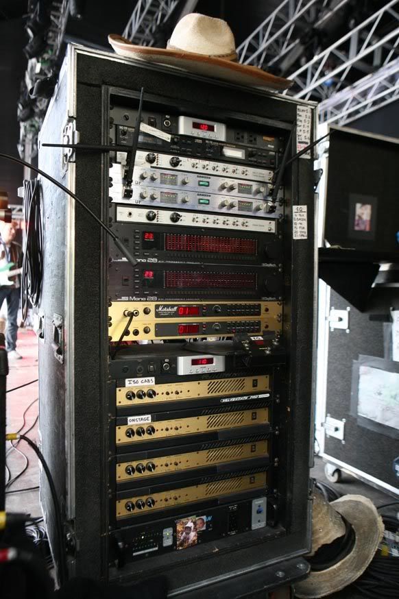
FWIW that's what Billy Gibbons does (and his sound is killer): a huge Rack, his preamp varies (although it's often a Marshall JMP1) , driving a few ...... Marshall 8008 power amps [img:582:874]http://i487.photobucket.com/albums/rr23 ... dy1wgl.jpg[/img]
I strongly suggest you download and read, first the introduction to Jack Darr's Guitar Amplifier Book (one chapter was already linked above) , google the other chapters which are available, of course best is to buy the full book (Amazon usually has a couple, sometimes used, worth every cent) and then follow with the best book on SS amps, period: Teemu Kyttala's http://www.thatraymond.com/downloads/so ... a_v1.0.pdf
I've just receipt a broken Marshall 8008 paid 25 euros and I would like to tweak it to find how can I like it,
Not much to tweak, sorry.
- C2 R2 and R1 make a highpass at 18 Hz; yes
- C1 and R1 make a lowpass at 10260 Hz;
no, the lowpass is C2 + R2 + whatever VR1 is set to, max 2k5 , so your lowpass is roughly 10k into 470pF , do the math (roughly 3X what you calculated early)
And it's not there for frequency compensation but to attenuate RF interference.
- C3 and R3 make a lowpass at 4800 Hz and set the gain together with previous network;
Yes to gain, that lowpass maybe meant to smooth a buzzy signal .
- C13 and R9 make a hifhpass shelving at 7200 Hz together with the TR7 and TR16 network;
R45 and R9 make a local feedback network, which allows the output stage to have a gain of ~4:1
What for?
The Op Amp output can not swing much more than +/-15V , and in fact 2 or 3 V less than that on each side, while speaker out must be able to swing +/-42 V , so output stage needs some local voltage gain, around 4X .
- D2 D3 R27 are a safety system for TR7 and TR16;
No, D2 D3 R27 bias Tr7 Tr16
- TR7 and TR16 drive the following HT supplyed power stage by the dual 15 V supply;
Sort of.
Tr7 Tr16 are called "level shifters" , whatever signal appearing at their emitters will also appear at their collectors , but "shifted" some 40 V , the DCV difference between the center rail and Tr2 Tr10 base, which sit close to power rails
Otherwise you would need a driver transformer to drive them from the Op Amp output.
- R45 is a sort of feedback, I guess;
- TR2 and TR10 drive the power stage;
- R24 R25 and TR5 are an amplified diode;
- TR1 and TR14 are the output transistors;
yes
- R13 and TR6 plus R34 and TR15 seems something like a compressor, a variable voltage divider that limits the pilotage of the power transistors as they increase the voltage swing;
Almost.
They are the short circuit protection.
Normally turned off, when current through R53 and R54 rise above ~8A they turn on ad limit/clamp/short base drive to power transistors.
- C22 and R59 are the zobel filter;
yes
But then...
- C19 R57 and R58... the cutoff frequency is 2 Hz, so what's its purpose? Why not just a resistor?
Also include C23 in the question.
Although 2 Hz is very low, it is not DC.
We do not want the amplifier to have DC gain because any small DC error at the input, called offset, will appear multiplied 20X or 40X at the output, which is bad, both to the speaker and the transistors.
- R55 is in parallel with R57 and R58, again why?
Not exactly.
Signal can always go through R55 while the one branched through R57 R58 will get different frequencies and voltages injected through C19 and depending on setting of SW2 switch.
By the way, that weird NFB network is the base of the "Valvestate" sound.
- how the CFB and VFB works exactly?
Can anyone please help me?
That merits another chapter in the book
I would like to adjust the response of this poweramp to my tastes, and with tube amps I know how to do it, while with this amp there are few points I'm missing.
Short anwer, you can't.
It's a very complex amplifier, very well designed, has been tweaked as much as is possible, anything you do will make it sound worse ... believe me.
Study a lot and design a preamp or distortion circuit or EQ or compressor aor anything else you want *outside* this Power Amp, *then* feed that into it (and into great speakers) .
FWIW that's what Billy Gibbons does (and his sound is killer): a huge Rack, his preamp varies (although it's often a Marshall JMP1) , driving a few ...... Marshall 8008 power amps [img:582:874]http://i487.photobucket.com/albums/rr23 ... dy1wgl.jpg[/img]
I strongly suggest you download and read, first the introduction to Jack Darr's Guitar Amplifier Book (one chapter was already linked above) , google the other chapters which are available, of course best is to buy the full book (Amazon usually has a couple, sometimes used, worth every cent) and then follow with the best book on SS amps, period: Teemu Kyttala's http://www.thatraymond.com/downloads/so ... a_v1.0.pdf
Design/Make/Service Musical stuff in Buenos Aires, Argentina, since 1969
Re: Schematic analysis of the Marshall Valvestate 8008
Thanks JM,
and sorry for the very late reply in thanking you for your help in all forums.
After some time I use it, I would like to remove the R3+C3 lowpass filter and lower the shelving of R9+C13.
I will update the forum on the results (is blown TIPs a result? ).
).
and sorry for the very late reply in thanking you for your help in all forums.
After some time I use it, I would like to remove the R3+C3 lowpass filter and lower the shelving of R9+C13.
I will update the forum on the results (is blown TIPs a result?