Blues Hound, you should change the PI plates to either 110K/120K or even 120K/130K. Your values are not "Dumble" and are "low" PI gain. Most Dumbles with this type of circuit, are in the ranges I mention when factoring in the trimmer.
Norm used low values, originally, because they used low wattage 6V6 amp design.
In addition, and this is uber-important, when you replaced the plates with 100k, did you also replace the cathode resistors with 1.5K? It is a must do....
Started DClone
Moderators: pompeiisneaks, Colossal
-
Blues Hound
- Posts: 143
- Joined: Sun Apr 09, 2006 1:58 am
Re: Started DClone
Bob-I: I am planning on reconnecting the wires you mentioned that are soldered to the side of the turetts. Hey I wanted to fire her up... 
Dogears: I will have to order the PI resistors as I only have 100K or 150K. Would you recommend going with 110K or 120K PI resistors? I am also planning on adding a FET simulating resistor to ground off of the last 2.2K in my dropping string, I believe you have suggested 150K. I will also be adding a 10pf cap on the Master Vol.
Thanks for the suggestions.
Steve
Re: Started DClone
Steve,
How about the cathode resistors? Are they 1.5K?
Definately use the 150K FET simulator. What are your voltages now?
110K/120K should suffice. I'd mod it for the 10K trimmer too. I definately hear and feel a change as it sweeps.
How about the cathode resistors? Are they 1.5K?
Definately use the 150K FET simulator. What are your voltages now?
110K/120K should suffice. I'd mod it for the 10K trimmer too. I definately hear and feel a change as it sweeps.
Blues Hound wrote:Bob-I: I am planning on reconnecting the wires you mentioned that are soldered to the side of the turetts. Hey I wanted to fire her up...
Dogears: I will have to order the PI resistors as I only have 100K or 150K. Would you recommend going with 110K or 120K PI resistors? I am also planning on adding a FET simulating resistor to ground off of the last 2.2K in my dropping string, I believe you have suggested 150K. I will also be adding a 10pf cap on the Master Vol.
Thanks for the suggestions.
Steve
-
Blues Hound
- Posts: 143
- Joined: Sun Apr 09, 2006 1:58 am
Re: Started DClone
Yes, I replced all cathode resistors with 1.5K.
I have two 120K RN65's to use for the PI.
I will see about adding a 10K trimmer, all ai have right now are 25K trimmers...
Steve
I have two 120K RN65's to use for the PI.
I will see about adding a 10K trimmer, all ai have right now are 25K trimmers...
Steve
Re: Started DClone
Then just add the 25K to your existing setup. Stick with the 91K/100K. Should be fine. Carbon film is fine for PI. Or, make it 100K/100K with the trimmer. Set to 112K/123K at first, then experiment.
Blues Hound wrote:Yes, I replced all cathode resistors with 1.5K.
I have two 120K RN65's to use for the PI.
I will see about adding a 10K trimmer, all ai have right now are 25K trimmers...
Steve
-
Blues Hound
- Posts: 143
- Joined: Sun Apr 09, 2006 1:58 am
Re: Started DClone
I am adding the 25K trimmer tonight, went and play some golf this afternoon... 
-
Blues Hound
- Posts: 143
- Joined: Sun Apr 09, 2006 1:58 am
Re: Started DClone
Well somethig is a mis...I add the 150K FET simulating resistor and here were the voltages I was getting:
V1 - CL1 & CL2
Pin 1 = 163 VDC - seems low
Pin 3 = 1.47
Pin 6 = 156 VDC
Pin 8 = 1.56
V2 - OD1 & OD2
Pin 1 = 175 VDC - again seems low
Pin 3 = 1.43
Pin 6 = 174 VDC
Pin 8 = 1.44
V3 - Reverb
Pin 1 = 426 VDC - (B+ 2)
Pin 3 = 2.50 VDC
Pin 6 = 167 VDC
Pin 8 = 1.37VDC
V4 - PI
Pin 1 = 272 VDC
Pin 2 = 37.0 VDC
Pin 3/8 = 57.1 VDC
Pin 6 = 286 VDC
Pin 7 = 35.2
V5 and V6 = 6L6GC RAC Blackplate Matched set
Pin 3 = 428 - seems low
PT is MM FBFBP-50 (Blackface Fender Bassman)
OT is MM FBFBM-OM (Blackface Fender Bassman)
So I pull the FET 150K resistor, and here are the new voltages:
V1 - CL1 & CL2
Pin 1 = 183 VDC - still seems low, shouldn't this be around 200 VDC?
Pin 3 = 1.62 VDC
Pin 6 = 176 VDC
Pin 8 = 1.73 VDC
V2 - OD1 & OD2
Pin 1 = 192 VDC - closer
Pin 3 = 1.56 VDC
Pin 6 = 192 VDC
Pin 8 = 1.58 VDC
V3 - Reverb
Pin 1 = 422 VDC (From B+2)
Pin 3 = 2.50 VDC
Pin 6 = 188 VDC
Pin 8 = 1.37 VDC
V4 - PI
Pin 1 = 279 VDC
Pin 2 = 35.7 VDC
Pin 3 = 56.9 VDC
Pin 6 = 281 VDC
Pin 7 = 36.6 VDC
V5 and V6
Pin 3 = 428 VDC
So, is there a problem with the PT???
Another thing I noticed was that as I was adjusting the bias, if I go past 37.5 ma, about 40% of the 10K pot, the bias jumps to 58 ma??? Is the bias pot bad?
Any help is appreciated...
V1 - CL1 & CL2
Pin 1 = 163 VDC - seems low
Pin 3 = 1.47
Pin 6 = 156 VDC
Pin 8 = 1.56
V2 - OD1 & OD2
Pin 1 = 175 VDC - again seems low
Pin 3 = 1.43
Pin 6 = 174 VDC
Pin 8 = 1.44
V3 - Reverb
Pin 1 = 426 VDC - (B+ 2)
Pin 3 = 2.50 VDC
Pin 6 = 167 VDC
Pin 8 = 1.37VDC
V4 - PI
Pin 1 = 272 VDC
Pin 2 = 37.0 VDC
Pin 3/8 = 57.1 VDC
Pin 6 = 286 VDC
Pin 7 = 35.2
V5 and V6 = 6L6GC RAC Blackplate Matched set
Pin 3 = 428 - seems low
PT is MM FBFBP-50 (Blackface Fender Bassman)
OT is MM FBFBM-OM (Blackface Fender Bassman)
So I pull the FET 150K resistor, and here are the new voltages:
V1 - CL1 & CL2
Pin 1 = 183 VDC - still seems low, shouldn't this be around 200 VDC?
Pin 3 = 1.62 VDC
Pin 6 = 176 VDC
Pin 8 = 1.73 VDC
V2 - OD1 & OD2
Pin 1 = 192 VDC - closer
Pin 3 = 1.56 VDC
Pin 6 = 192 VDC
Pin 8 = 1.58 VDC
V3 - Reverb
Pin 1 = 422 VDC (From B+2)
Pin 3 = 2.50 VDC
Pin 6 = 188 VDC
Pin 8 = 1.37 VDC
V4 - PI
Pin 1 = 279 VDC
Pin 2 = 35.7 VDC
Pin 3 = 56.9 VDC
Pin 6 = 281 VDC
Pin 7 = 36.6 VDC
V5 and V6
Pin 3 = 428 VDC
So, is there a problem with the PT???
Another thing I noticed was that as I was adjusting the bias, if I go past 37.5 ma, about 40% of the 10K pot, the bias jumps to 58 ma??? Is the bias pot bad?
Any help is appreciated...
-
Blues Hound
- Posts: 143
- Joined: Sun Apr 09, 2006 1:58 am
Re: Started DClone
Well, I decided to:
1. Make a new preamp board
2. Move the filter caps up into the chassis
3. Clean up the lead dress
Here are some pictures of what I have done so far:
New Preamp Borad
[img 768]http://i394.photobucket.com/albums/pp25 ... edo004.jpg[/img]
Filter Caps
[img768]http://i394.photobucket.com/albums/pp25 ... edo003.jpg[/img]
I am working on the Channel and PAB switching now...
Steve
1. Make a new preamp board
2. Move the filter caps up into the chassis
3. Clean up the lead dress
Here are some pictures of what I have done so far:
New Preamp Borad
[img
 768]http://i394.photobucket.com/albums/pp25 ... edo004.jpg[/img]
Filter Caps
[img
768]http://i394.photobucket.com/albums/pp25 ... edo003.jpg[/img]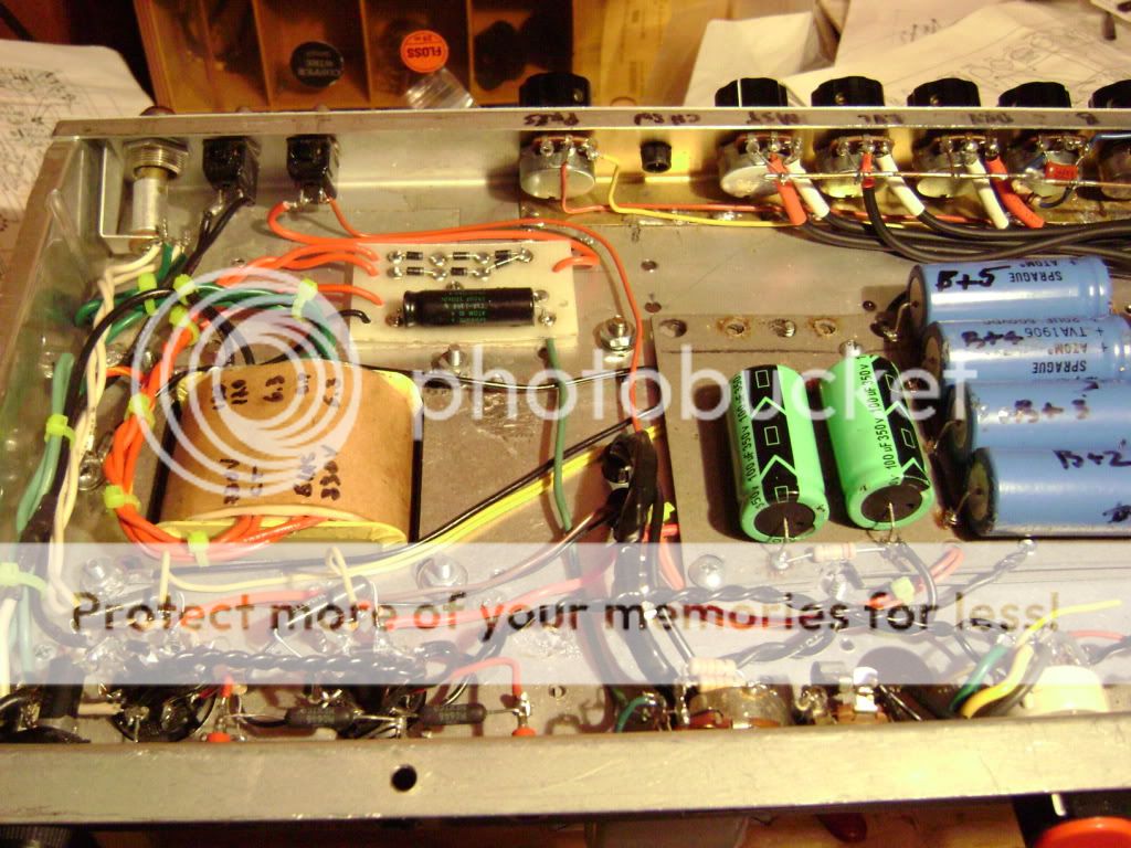
I am working on the Channel and PAB switching now...
Steve
Re: Started DClone
that filter cap board looks so close to the chassis. Make sure no cap leads are touching ground.
**************************
Failure is not an option... it comes bundled with the kit.
Failure is not an option... it comes bundled with the kit.
Re: Started DClone
Very nice!!! I think you've inspired me to finally rebuild my Bassman. 
(I've been threatening to tear it apart for years but just never seem to find the inspiration.)
(I've been threatening to tear it apart for years but just never seem to find the inspiration.)
Re: Started DClone
It looks like he as backer board on the power boards. It should pose a problem but I like to see them a little higher off the chassis as well.fp2000 wrote:that filter cap board looks so close to the chassis. Make sure no cap leads are touching ground.
Tom
Don't let that smoke out!
Don't let that smoke out!
-
Blues Hound
- Posts: 143
- Joined: Sun Apr 09, 2006 1:58 am
Re: Started DClone
Norm,
It is your basically your Bassman Clone with #124 values and swithcing. I will pm you the board layout I did if you like.
Structo,
I am thinking of adding strandoffs.
Steve
It is your basically your Bassman Clone with #124 values and swithcing. I will pm you the board layout I did if you like.
Structo,
I am thinking of adding strandoffs.
Steve
Re: Started DClone
Looks good! I think you will like it even better with the new layout!
Re: Started DClone
Must either jumper the bass pot lugs or run to a relay like HAD did. In normal operation the input and wiper lugs are connected. That is the Dumble way. Also, I'd use a .01uf midcap if you use a 150K slope. If you use a .05 midcap, try the classic stack with 100K slope. Again, the Dumble way.... (in the overwhelming majority of cases)
-
Blues Hound
- Posts: 143
- Joined: Sun Apr 09, 2006 1:58 am
Little Help Please
Well, everything is done, voltages at V1, V2, V3 area fine:
V1 CL1 and CL2:
Pin 1 = 185 VDC
Pin 2 = 0.7 mv
Pin 3 = 1.794 VDC
Pin 6 = 185 VDC
Pin 7 = 0.7 mv
Pin 8 = 1.798 VDC
V2 OD1 and OD2:
Pin 1 = 211 VDC
Pin 2 = 0.7 mv
Pin 3 = 1.518 VDC
Pin 6 = 212 VDC
Pin 7 = .06 mv
Pin 8 = 1.509 VDC
V3 PI:
Pin 1 = 293 VDC
Pin 2 = 37.8 VDC
Pin 3 and Pin 8 = 60.3 VDC
Pin 6 = 294 VDC
Pin 7 = 38.7 VDC
V4 Reverb:
Pin 1 = 442 VDC
Pin 2 = 4.4 mv
Pin 3 = 3.24 VDC
Pin 6 = 171.7 VDC
Pin 7 = 0.1 mv
Pin 8 = 1.99 VDC
But I seem to have a problem with the 12v supply to the relays.
Here is a picture of the board:
[img768]http://i394.photobucket.com/albums/pp25 ... edo013.jpg[/img]
[img768]http://i394.photobucket.com/albums/pp25 ... edo026.jpg[/img]
It is basically the same board as #124, but I am only getting .526 VDC at the output on the 12 v regulator...any help is greatly appreciated...
Steve
V1 CL1 and CL2:
Pin 1 = 185 VDC
Pin 2 = 0.7 mv
Pin 3 = 1.794 VDC
Pin 6 = 185 VDC
Pin 7 = 0.7 mv
Pin 8 = 1.798 VDC
V2 OD1 and OD2:
Pin 1 = 211 VDC
Pin 2 = 0.7 mv
Pin 3 = 1.518 VDC
Pin 6 = 212 VDC
Pin 7 = .06 mv
Pin 8 = 1.509 VDC
V3 PI:
Pin 1 = 293 VDC
Pin 2 = 37.8 VDC
Pin 3 and Pin 8 = 60.3 VDC
Pin 6 = 294 VDC
Pin 7 = 38.7 VDC
V4 Reverb:
Pin 1 = 442 VDC
Pin 2 = 4.4 mv
Pin 3 = 3.24 VDC
Pin 6 = 171.7 VDC
Pin 7 = 0.1 mv
Pin 8 = 1.99 VDC
But I seem to have a problem with the 12v supply to the relays.
Here is a picture of the board:
[img
768]http://i394.photobucket.com/albums/pp25 ... edo013.jpg[/img]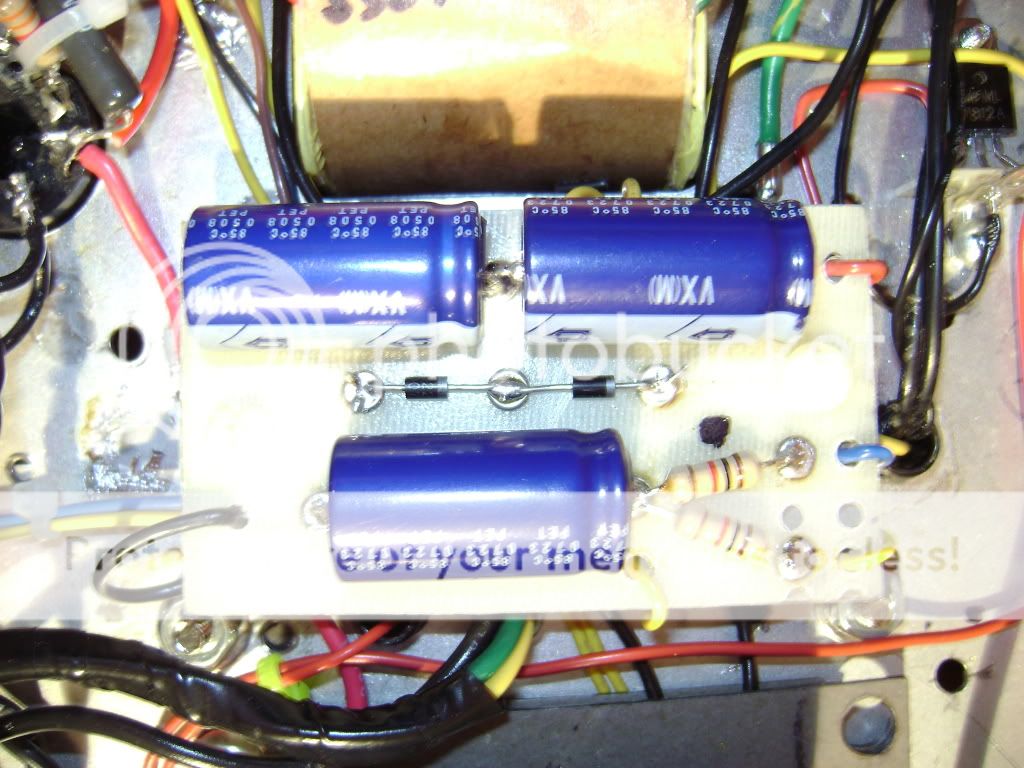
[img
768]http://i394.photobucket.com/albums/pp25 ... edo026.jpg[/img]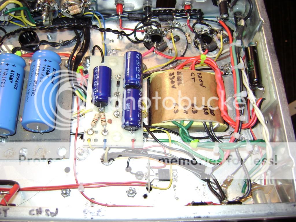
It is basically the same board as #124, but I am only getting .526 VDC at the output on the 12 v regulator...any help is greatly appreciated...
Steve