Bias problem after change the output transformer.

Overdrive Special, Steel String Singer, Dumbleland, Odyssey, Winterland, etc. -
Members Only

Moderators: pompeiisneaks, Colossal

Post Reply
psychepool
Posts: 286
Joined: Fri Apr 18, 2014 8:29 am

Bias problem after change the output transformer.

Post by psychepool »

I made a Dumble clone with 20W, and now remake with 35W.
The changed parts are just output transformer and power supply components.
Output trans is changed with Hammond 1760J.(Vibrolux Reverb replacement) The 20W version used Hammond 1760H.(Deluxe Reverb replacement)
The electrolytic was radial type, but changed with nichicon 100uF Axial type, and for PI/Preamp use JJ Tesla 40/20/20/20uF Multi-section can type.
Power trans dosen't changed.(320-50-0-320)
Output tube dosen't changed too.(Tung-sol reissue 5881)

When I make it complete and turn the stand-by on, there's loud hum noise.
There's even squeal oscillation.
When swap the output transformer primary line, the oscillation has disappears. But hum is still exist.

I check the bias on Pin8. It's about 200mA!
I change some component on bias circuit and turn the bias pot, but the bias drop is not enough.(It dosen't drop below about 180mA)

Every pots and relay switches are operate.
But guitar sound has somthing strange.
It feels like very short time delay or ring modulator. Trembled like subtle dissonance.

Everything is the same, except the output trans and power supply capacitors.
Output tube is also the same.(The 20W version also used TS 5881)
The multiple can-type capacitor may be the matter?
It dose not feel the lack of power transformer's current.
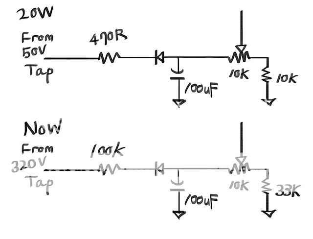
May be the 50v tap for the bias circuit matter?
How about supply the bias voltage from the 320v tap with about 100K resistor?


If there is a problem that can be inferred from the above symptoms, please answer.
Thanks. :)
User avatar
martin manning
Posts: 14308
Joined: Sun Jul 06, 2008 12:43 am
Location: 39°06' N 84°30' W

Re: Bias problem after change the output transformer.

Post by martin manning »

Pull the output tube and check the voltage on socket pin 5. You should be able to get it down to around -50V with the bias trimmer. If not, your bias circuit needs work. A schematic is worth a thousand words.
psychepool
Posts: 286
Joined: Fri Apr 18, 2014 8:29 am

Re: Bias problem after change the output transformer.

Post by psychepool »

Thanks martin.
When I tried that you say, the pin5 was -25v.
So I tried to change the bias voltage supply.
I disconnect 50v tap, and connect to 320vac main.
Pull-down resistor(?) 470R is replaced with 100K.
Then pin5 gets -45v!

But when I put the output tube and power on, the bias is still high.
It's about 80~100mA.
Even the pin5 still gets -45v.

I will try the 100K resistor lower, but does it can be the fundamental solution?

The schematic is typical dumble overdrive special.
I use JJ Tesla 40/20/20/20 multi-cantype capacitor instead of 22uF x 4.

Which error can be infer in this case?
User avatar
martin manning
Posts: 14308
Joined: Sun Jul 06, 2008 12:43 am
Location: 39°06' N 84°30' W

Re: Bias problem after change the output transformer.

Post by martin manning »

You were headed in the right direction getting the idle current down to 100mA. With a 50V bias tap I would use: 470 ohm resistor -> Diode -> 100uF cap to ground -> 10k pot with wiper to 2x 220k resistors, and a 27k resistor to ground from the other end of the pot. That should get you around -60V.
psychepool
Posts: 286
Joined: Fri Apr 18, 2014 8:29 am

Re: Bias problem after change the output transformer.

Post by psychepool »

10k pot with wiper to 2x 220k resistors
<- I don't know what means "wiper to 2 x 220K resistors".

Here's my bias schmatic.

http://i935.photobucket.com/albums/ad19 ... 1462762139

I want to know what means "10k pot with wiper to 2x 220k resistors".
Please explain through the circuit.
User avatar
martin manning
Posts: 14308
Joined: Sun Jul 06, 2008 12:43 am
Location: 39°06' N 84°30' W

Re: Bias problem after change the output transformer.

Post by martin manning »

The wiper is the center terminal on the pot, which is the output of the bias supply. That connects to the junction of two (usually) 220k resistors on the main board.

In the upper bias circuit schematic using the 50V tap, the 10k to ground is too small. If you make that a 27k, it should work fine.
psychepool
Posts: 286
Joined: Fri Apr 18, 2014 8:29 am

Re: Bias problem after change the output transformer.

Post by psychepool »

Ok I can understand what "wiper" means.

You said 27K be ok, but I also tried other resistor value to the ground, the bias was not changed enough even applyed 2.2M.

I will try another value insted of 100k 3W. (from 320vac tap)

Is there another reason to think you are? For example wrong grounding, and etc...
larsvictor
Posts: 152
Joined: Wed Sep 23, 2009 12:00 pm
Location: Germany

Re: Bias problem after change the output transformer.

Post by larsvictor »

Hi psychepool,

I had almost the same problem two weeks ago: After 10 minutes playing loud hum and redplating on all power tubes. Idle current was > 150 mA. Negative voltage on pin(s) 5 was -23 VDC, approx. half of what it is supposed to be.

It was a bad 100µF capacitor in the bias voltage network. No filtering anymore and with only one diode rectifiing there was the full ripple 0 to -50 VDC on the grids. My DMM (DC) took the mean.

Victor
psychepool
Posts: 286
Joined: Fri Apr 18, 2014 8:29 am

Re: Bias problem after change the output transformer.

Post by psychepool »

Oh, victor. Your expect was right!

When I checked the 100uF capacitor for replace new one, I found that the ground from 100uF is not connected!
I connect 100uF to ground and now it has no hum! Bias can adjust 4mA~50mA. Very nice!

Causes of difficult problems has always been a simple place.
These kind of problems always makes me collapsed. :)

Just one disappoint is the output level is not louder than I expected.
Decided to change the OT was for get more clean headroom.
It gets little bit louder but the amount is not enought with my expection.
But anyway, the sound is still good, and all function is alright!

Here is my dunble 35W gutshot.

http://s935.photobucket.com/user/psyche ... sort=1&o=2
http://s935.photobucket.com/user/psyche ... sort=1&o=0
http://s935.photobucket.com/user/psyche ... sort=1&o=3
http://s935.photobucket.com/user/psyche ... sort=1&o=1

The chissis size is almost the same with Orange tiny Terror.
Because of the small size it was hard to build, but the result feels so rewarding.
Next, I will make head cabinet for complete this amp.

Thank you very much Victor and Martin!
User avatar
martin manning
Posts: 14308
Joined: Sun Jul 06, 2008 12:43 am
Location: 39°06' N 84°30' W

Re: Bias problem after change the output transformer.

Post by martin manning »

Are you using the 50V tap as the source? I recommend that you do since the bias voltage will stabilize much more quickly.
psychepool
Posts: 286
Joined: Fri Apr 18, 2014 8:29 am

Re: Bias problem after change the output transformer.

Post by psychepool »

Yes, from 50v tap.
I realize the real cause so there's no reason to supply from 320v tap.

Thanks for your recommend. :)
User avatar
drew
Posts: 731
Joined: Wed Jun 21, 2006 2:49 am

Re: Bias problem after change the output transformer.

Post by drew »

psychepool wrote:
The chissis size is almost the same with Orange tiny Terror.
Because of the small size it was hard to build, but the result feels so rewarding.
That's a good looking amp. Glad you got it squared away.
Post Reply