Hello fellows, I want to try two MOSFETs as source followers to drive the output from the phase inverter on my AB763 blackface amp.
In short I've done most of the 64 Vibroverb Custom mods to the amp. Even a larger OT. Look at the Deluxe Reverb schematic to picture the MOSFET source followers between the phase inverter and output tubes.
I don't use the tremolo often, so I could hack it up and use that socket as a DC coupled cathode follower for this with a 12AU7, but I like the idea of the MOSFETs better. From my reading MOSFET source followers lose less gain from the previous stage and are more linear than a triode used as a cathode follower driver. Plus they do not draw any filament current because they do not require it.
My understanding of a cathode follower or a MOSFET source follower is the goal is to prevent cross over distortion due to bias shift and to prevent distortion due to grid current limiting.
I learned about using MOSFETs as source followers in R.G. Keen's MOSFET follies article. Just Google MOSFET follies.
In text here is how I think it is done. I may be wrong, so if so please guide me. I am very low vision so my learning of this is limited.
The drain for both MOSFETs receive B+ from the Phase Inverters B+ supply.
The connection between R54 (82K plate resistor for V6A) and C27 (0.1uF 630V coupling cap) is cut.
The connection between R55 (100K plate resistor for V6B) and C28 (0.1uF 630V coupling cap) is cut.
The cut wire from R54 is wired to MOSFET #1's gate through a 220R 1/2W resistor.
The cut wire from R55 is wired to MOSFET #2's gate through a 220R 1/2W resistor.
MOSFET #1's source goes to ground through an 82K 1/2W resistor.
MOSFET #2's source goes to ground through a 100K 1/2W resistor.
MOSFET #1's source is wired to C27.
MOSFET #2's source is wired to C28.
I believe that does it. Does that sound right?
I know I'll need to rebias the amp. Will anything else need to be changed or is it that simple?
MOSFET source follower for output stage of AB763 blackface
Moderators: pompeiisneaks, Colossal
-
SixStringBender
- Posts: 93
- Joined: Sat Nov 01, 2014 4:17 am
- Location: USA
Re: MOSFET source follower for output stage of AB763 blackface
I'd like to try this as well
www.myspace.com/20bonesband
www.myspace.com/prostitutes
Express, Comet 60, Jtm45, jtm50, jmp50, 6g6b, vibroverb, champster, alessandro rottweiler
4x12" w/H75s
www.myspace.com/prostitutes
Express, Comet 60, Jtm45, jtm50, jmp50, 6g6b, vibroverb, champster, alessandro rottweiler
4x12" w/H75s
Re: MOSFET source follower for output stage of AB763 blackface
I think this is regarding a DRRI?
The MOSFET follies idea for phase splitter buffer (as I understand it) was to direct couple the power tube control grids to a low impedance driver, so as to facilitate AB2 operation.
Capacitively coupling a low impedance driver will likely maintain AB1 whilst exacerbating bias excursion under overdrive.
However, if direct coupling was implemented, operating an amp designed for AB1 in AB2 may be likely to put additional stress on the power supply, power tubes and OT.
A review should be undertaken to ensure they can accommodate this.
A skim over tube information sheets indicates that operating conditions for AB2 tend to be rather different to AB1, eg for 6L6 http://www.mif.pg.gda.pl/homepages/fran ... /6L6GC.pdf as I can't find a 6V6 info sheet with AB2.
Does any commercial guitar amp use AB2?
https://www.justgiving.com/page/5-in-5-for-charlie This is my step son and his family. He is running 5 marathons in 5 days to support the research into STXBP1, the genetic condition my grandson Charlie has. Please consider supporting him!
-
martin manning

- Posts: 14308
- Joined: Sun Jul 06, 2008 12:43 am
- Location: 39°06' N 84°30' W
Re: MOSFET source follower for output stage of AB763 blackface
According to RG's description in his MOSFET Follies, this has been done before with good results. The description by SSB above does not match RG's, and ignores the need for a separate bipolar power supply, and possibly separate bias supplies for the MOSFET's. I believe the proposed MOSFET driver concept would be implemented as shown below. Maybe RG himself can comment...
PDF, no one said you have to drive the output tubes into AB2, but you could. Staying in AB1, the benefit would be in reducing bias excursion and blocking.
Edit: added a 12V Zener to protect 20V Vgs, changed MOSFET type to IRF820.
(see later version below with suggested bipolar power supply)
PDF, no one said you have to drive the output tubes into AB2, but you could. Staying in AB1, the benefit would be in reducing bias excursion and blocking.
Edit: added a 12V Zener to protect 20V Vgs, changed MOSFET type to IRF820.
(see later version below with suggested bipolar power supply)
Last edited by martin manning on Mon Apr 13, 2015 11:00 am, edited 2 times in total.
Re: MOSFET source follower for output stage of AB763 blackface
Wouldn't it be an inevitable consequence though, unless action was taken to prevent it, eg larger grid stoppers?PDF, no one said you have to drive the output tubes into AB2
https://www.justgiving.com/page/5-in-5-for-charlie This is my step son and his family. He is running 5 marathons in 5 days to support the research into STXBP1, the genetic condition my grandson Charlie has. Please consider supporting him!
-
SixStringBender
- Posts: 93
- Joined: Sat Nov 01, 2014 4:17 am
- Location: USA
Re: MOSFET source follower for output stage of AB763 blackface
pdf64, lol, you got me. I am the LipstickMan from the other forum. I figured The Amp Garage would be a nice place to run this idea. I wanted to leave the DR "reissue" out of it so I will get more help and no comments saying PCB is hard to mod. I know it is, but it's all I got and I don't mind modding it. I just need guidance from you smart fellows. We have experience cutting, drilling and scraping traces. Eventually I may understand enough to build a handwired amp and lay it out with plenty of room for future mods as I learn.
martin manning, I figured I was leaving something out. I could tell from Keen's description I may not have it exactly right. I'm a really low vision guy, legally blind since childhood, so I'll have to have my wife run the schematic you posted by me. Everything I've learned has been with her telling me this goes to that, and that goes to this. lol It's been hard to learn.
If one of you will, can you give a text description of the schematic martin manning posted so it will help me grasp this? It seems it isn't as simple as a cathode follower or MOSFET source follower for a tone stack. If I completely understand what is going on I can guide my helper when we mod the amp. My helper can solder, but has no clue what we're ever doing. First priority is always safety, so don't worry.
I'll now sit back and let you guys figure out exactly how it is done. Then we'll hack my amp up once again. lol
-
SixStringBender
- Posts: 93
- Joined: Sat Nov 01, 2014 4:17 am
- Location: USA
Re: MOSFET source follower for output stage of AB763 blackface
Okay, we just went over the schematic. So it isn't DC coupled to the PI plates. It goes in after the coupling caps. I think I understand that part of it now.
martin, isn't the way I originally posted my idea biasing the MOSFET's separately? I had an 82K bias resistor on MOSFET 1's source to ground and a 100K on MOSFET 2's source to ground. I was matching the plate resistors for V6A and V6B. I don't know if that is correct or not, lol, but that was the idea. Maybe this is what you were saying I did wrong?
What I don't understand is the power to the MOSFET in the schematic. I need help with that.
Here is how I understand it using the MOSFET for the V7 output side. Ignore the other.
Connection between C27-R56 and R60 is cut (leaving R56 connected to C27). The C27-R56 junction go to the gate of the MOSFET through a 220R 1/2W resistor.
The source goes to R60.
I also just caught something else. The source isn't biasing to ground through a resistor?
And the power to drain. I'm lost.
-
martin manning
- Posts: 14308
- Joined: Sun Jul 06, 2008 12:43 am
- Location: 39°06' N 84°30' W
Re: MOSFET source follower for output stage of AB763 blackface
If you were to connect the FET's source resistor to ground, the source pin would be sitting at a positive voltage. You need it to be at the power tube's grid bias voltage, about -37V according to the schematic. The source resistor will drop another 30-40 volts, so the source supply voltage has to be at something like 80-100 volts below ground.
You don't want the source resistor to be too large either- remember the goal is a low impedance driver. The miss-matched PI plate load resistors have to do with balancing the PI outputs, and are not related to the bias voltages.
The FET's drain voltage has to be above ground so that the source pin can swing up to and above ground if the power tube grids are to be driven positive. So you need to create both a negative and a positive supply for the drivers.
-
SixStringBender
- Posts: 93
- Joined: Sat Nov 01, 2014 4:17 am
- Location: USA
Re: MOSFET source follower for output stage of AB763 blackface
Okay, it is beginning to make more sense to me now. I read your reply and reread Keen's article. Both your-alls descriptions are saying the same thing. I see what my mistakes were now. I can now understand what is being said, but I still don't know how to connect the drain and source entirely. I'm gonna have my wife go over it with me more later. Maybe I can get an understanding of it better now since I know the idea of what is happening.
For now, I have a question. Why are the 1.5K control grid resistors needed? Keen's article mentions the source follower or cathode follower is directly coupled to the control grid of the output tube.
Since the output impedance of the source follower is so low are the control grid resistors needed? Or maybe reduced? Since providing current is the goal. It seems a resistor takes the whole "direct coupled" idea out of it.
Forgive me if I sound stupid. lol I'm learning and want to ask, even if it sounds stupid. I'll not know if I don't ask. lol
-
martin manning
- Posts: 14308
- Joined: Sun Jul 06, 2008 12:43 am
- Location: 39°06' N 84°30' W
Re: MOSFET source follower for output stage of AB763 blackface
Grid stoppers on the output tubes is still a good idea to prevent oscillations, and a lower value would probably work for that purpose. The source follower is still direct coupled, as opposed to capacitively coupled. I don't think there would be much difference in sound, but it's something to try.
The source and drain have to be connected to -100V and +100V supplies, which you don't have at the moment. You could possibly derive these supplies from the existing PT secondary, but I think a better solution would be to add a small transformer and make a bipolar supply. It wouldn't hurt if the +/- voltages were higher, as long as the FET can take it... IRF820 is a 500V part so no problem there. A transformer with dual 120V secondaries would be easy to find, would produce +/- ~160V, which would work well for amps with bigger power tubes requiring more negative voltage.
The source and drain have to be connected to -100V and +100V supplies, which you don't have at the moment. You could possibly derive these supplies from the existing PT secondary, but I think a better solution would be to add a small transformer and make a bipolar supply. It wouldn't hurt if the +/- voltages were higher, as long as the FET can take it... IRF820 is a 500V part so no problem there. A transformer with dual 120V secondaries would be easy to find, would produce +/- ~160V, which would work well for amps with bigger power tubes requiring more negative voltage.
-
SixStringBender
- Posts: 93
- Joined: Sat Nov 01, 2014 4:17 am
- Location: USA
Re: MOSFET source follower for output stage of AB763 blackface
Oh, I see about the control grid resistors. Makes sense.
I've read and reread the MOSFET follies article.
A quote from the MOSFET follies article. "This means that the cathode resistor is tied to a more negative voltage of something more than twice the bias voltage, so it can pull the output tube grid negative."
According to this, I think there should be a "cathode resistor" between the cathode tube pin and the -100V supply. In the case of the MOSFET, a source resistor between the MOSFET's source and the -100V supply???
Another quote from the MOSFET follies article. "The follower is set up so that its cathode sits at the normal negative bias voltage of the output tube, maybe -10V to -40V depending on the tube type. This means that the cathode resistor is tied to a more negative voltage of something more than twice the bias voltage, so it can pull the output tube grid negative."
I don't understand how the cathode follower is set up so it is at the normal negative bias of the output tube. Unless this is done by choosing a cathode bias resistor that will do so by resisting the -100V supply??? Again, in the case of the MOSFET, a source resistor instead of a cathode resistor from source to the -100V supply.
Wouldn't a transformer's secondaries have to be rectified and set up to be switched on using two relays when the standby is switched ON (a relay for the positive DC lead and a relay for the negative DC lead)?
And I'm learning, so I don't know how to do this. I'm just grasping the concept, I think.
I'll give it a shot though. How about drilling the chassis for another octal socket and installing one of those SS plug in rectifiers (rectifier rectifies the new transformer's AC to DC)? Then from there wire the positive to the drain and the negative to the source resistor through the relays and filter caps?
I assume, since the relays share the same ground (chassis) as the transformers, the fact the power from the standby switch comes from another transformer (the main power transformer) that the standby switch will be able to trigger the relays?
Or just defeat the stinking standby switch and wire the rectified DC positive to the drain and the rectified DC negative to the source. Through filter caps.
Don't need that mute switch anyway. From all my reading it does more harm than good. I never power down with it in standby because that causes the filter caps to store high voltage. If you power down with hot tubes with the standby switch in the play position the output tubes will drain the caps. Don't need the stinkin' standby switch.
Also, I assume the transformer's primaries would be tapped into the power switch with the main power transformer's primaries.
what prevents the DC from getting to the output tube without a coupling cap?
Sorry for the book and all the questions. I want to know exactly what I'm doing before I attempt any of this.
-
SixStringBender
- Posts: 93
- Joined: Sat Nov 01, 2014 4:17 am
- Location: USA
Re: MOSFET source follower for output stage of AB763 blackface
I have yet another thought, that may be the best yet.
We have 120VAC already. Why need a transformer with a center tap.
How about a two way bridge rectifier wired directly off the power switch?
We have 120VAC already. Why need a transformer with a center tap.
How about a two way bridge rectifier wired directly off the power switch?
-
Kagliostro

- Posts: 549
- Joined: Wed Dec 30, 2009 12:09 am
- Location: Italy
Re: MOSFET source follower for output stage of AB763 blackface
May this be of some interest ?
[img 1240]http://www.jogis-roehrenbude.de/Roehren ... loso-s.jpg[/img]
K
[img
 1240]http://www.jogis-roehrenbude.de/Roehren ... loso-s.jpg[/img]
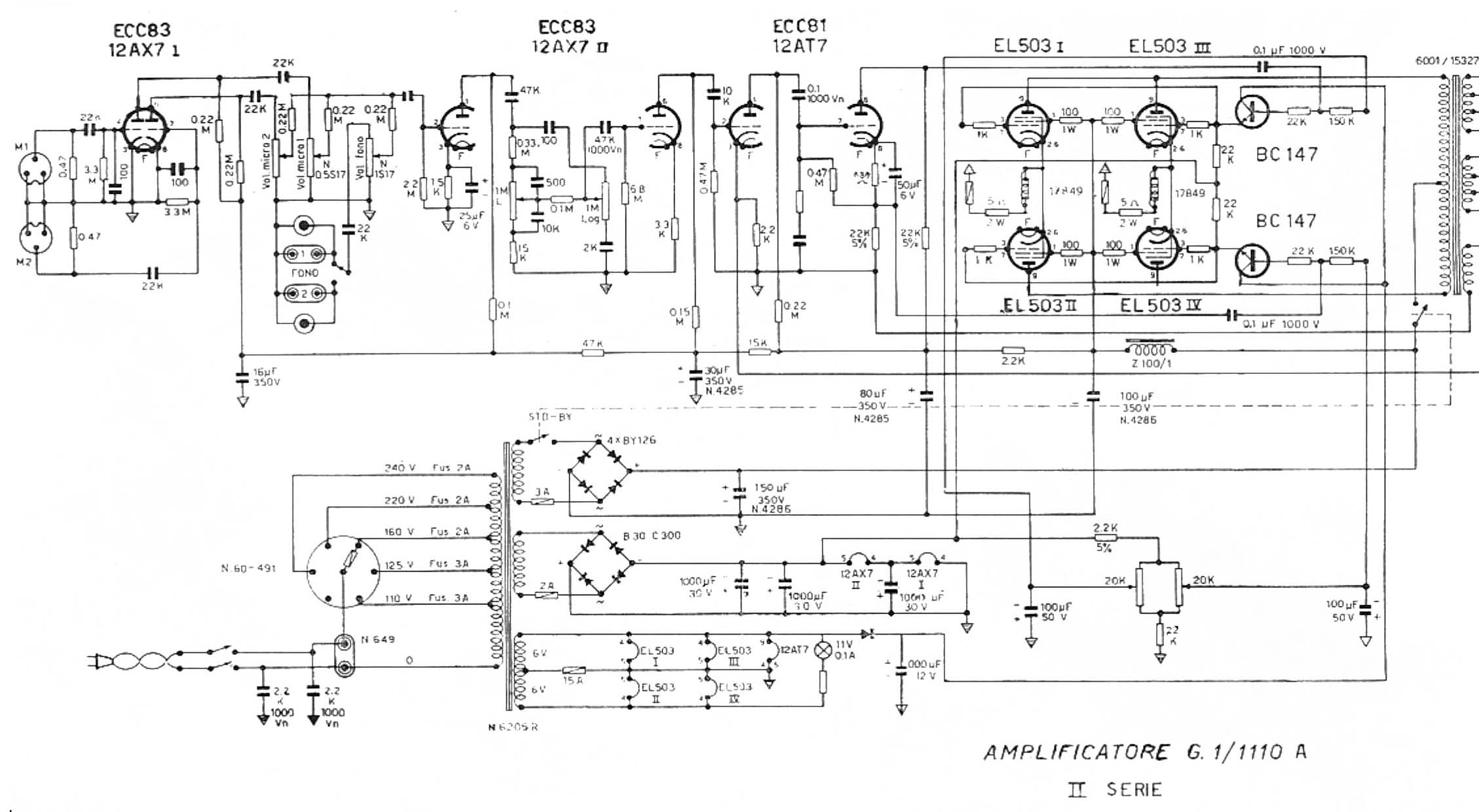
K
Re: MOSFET source follower for output stage of AB763 blackface
Because now the amplifier chassis is hot to the AC power line and is both a shock and a fire hazard.SixStringBender wrote:We have 120VAC already. Why need a transformer with a center tap.
How about a two way bridge rectifier wired directly off the power switch?
-
martin manning
- Posts: 14308
- Joined: Sun Jul 06, 2008 12:43 am
- Location: 39°06' N 84°30' W
Re: MOSFET source follower for output stage of AB763 blackface
Bad idea. You need a transformer to isolate the chassis from the AC line. Ideally you'd want a ~150V CT (75-0-75) transformer to get +/-100V.
No need to involve the standby switch in any of this. Think of the MOSFET circuit as just another bias supply which, just like the original, comes up (well, down, really...) as soon as you switch on the main power. The amp's bias supply is being repurposed in this scheme, as it becomes the bias supply for the MOSFET.
Yes, there is a source resistor between the -100V supply and the FET's source pin, it's shown that way in the schematic I posted. The voltage rises as the current flows from the -100V supply up to the source pin, just like it does in any cathode follower. The trick here is that you are adjusting the current through the FET such that the voltage at the source pin matches the power tube bias voltage requirement, which is something higher than -100V, -37V in your case.