two voltage dividers one after another?
Moderators: pompeiisneaks, Colossal
-
iknowjohnny
- Posts: 1070
- Joined: Thu Apr 24, 2008 2:10 am
- Location: los angeles
two voltage dividers one after another?
But......one being a variable volume pot. What i'm wondering is whether putting a 1M/1M VD before my pre pi master to knock down the volume to the PI would have any repercussions. My amp is just stupid loud and the master is very sensitive. I recall trying this in the past but i think it changed the tone too much but i may not be remembering right or i may have used smaller resistors and the lower load may have not been a good thing. Been quite a while. Anyways, i just wanted to see if there are any theoretical reasons it wouldn't be a good idea. Before i yank the chassis and try it again.
-
martin manning

- Posts: 14308
- Joined: Sun Jul 06, 2008 12:43 am
- Location: 39°06' N 84°30' W
Re: two voltage dividers one after another?
If the volume pot is a 1M now, and you don't want to change it, put a 470k-1M voltage divider in front of it (1M in parallel with the pot element). That will give you a 6dB reduction and preserve the frequency response.
-
iknowjohnny
- Posts: 1070
- Joined: Thu Apr 24, 2008 2:10 am
- Location: los angeles
Re: two voltage dividers one after another?
I've tried that. In fact, i've tried lots of things that seem to change the tone too much. I just can't wrap my head around this arrangement as far as considering what could be going on with the series and parallel resistors if you know what i mean.martin manning wrote:If the volume pot is a 1M now, and you don't want to change it, put a 470k-1M voltage divider in front of it (1M in parallel with the pot element). That will give you a 6dB reduction and preserve the frequency response.
EDIT: wait....I may have misunderstood. Can you clarify whether you mean strap a resistor across the pot and nothing else, or adding 2 resistors as a VD as i described? not sure because you said "put a 470k-1M voltage divider in front of it", but then you said put 1M in parallel with the pot which is not what a VD in front of it would do. The series R would be in series with the pot element.
Re: two voltage dividers one after another?
The solution that Martin describes keeps the load the same (1M) and will not change your "tone". It does exactly what you asked for (cut the level but keep the load the same). Your other option would be to put a 470K resistor in series with a 500K pot--which is electrically the same as what Martin describes but with a slightly different taper. But, you have already tried that too and it changed your tone, right?
The formulas for series and parallel resistors are very simple and basic electronics theory. It's the first thing you should learn.
The formulas for series and parallel resistors are very simple and basic electronics theory. It's the first thing you should learn.
What?
-
iknowjohnny
- Posts: 1070
- Joined: Thu Apr 24, 2008 2:10 am
- Location: los angeles
Re: two voltage dividers one after another?
If by the formulas you mean 1M = 1M in parallel=500k or 1M = 1M in series =2M, i get that. Thats not what i meant by can't wrap my head around it. But as for martin's suggestion, as i said in the edit in my last post, it wasn't clear to me what he was suggesting.
-
martin manning
- Posts: 14308
- Joined: Sun Jul 06, 2008 12:43 am
- Location: 39°06' N 84°30' W
Re: two voltage dividers one after another?
1M is in parallel with the pot:iknowjohnny wrote:Can you clarify whether you mean strap a resistor across the pot and nothing else, or adding 2 resistors as a VD as i described? not sure because you said "put a 470k-1M voltage divider in front of it", but then you said put 1M in parallel with the pot which is not what a VD in front of it would do. The series R would be in series with the pot element.
You do not have the required permissions to view the files attached to this post.
-
iknowjohnny
- Posts: 1070
- Joined: Thu Apr 24, 2008 2:10 am
- Location: los angeles
Re: two voltage dividers one after another?
Ok, yes, thats what i have tried and it does change the tone because it halfs the load. let me just ask this....if i did what I first suggested, will that also half the load? The load part of a set VD is also 1M to ground, but it's separated from the pot's load unless the pot is maxed. Come to think of it, it may not be that your method changed the tone but just didn't cut gain much. In fact i'm pretty sure thats why i dropped that idea.
In any case, what are the possible repercussions of doing what i suggested?
In any case, what are the possible repercussions of doing what i suggested?

Re: two voltage dividers one after another?
I think any sort of volume reduction or attenuation/MV or whatever, at any point in the amp, changes the tone of an amp.
It could be because of the effect of loudness on what we perceive as tone.
Often this can be adjusted out with the tone controls.
An easy mod you could try would be the Carlsbro/Mojave mod that uses a pot to lower the PI bias, which lowers the output from the PI to the power tubes (you could call it a cold-clipper PI).
I used it in this Talon amp, and it worked, many customers loved it, and others have a variety of opinions about how it sounds or whether it's "good design" or not, but it only takes one pot to try it.
Just put a pot (I used a 50K-L) in series with the PI shared cathode resistor. The pot could be from 25K to 250k, and you'll probably hear the general result of doing it this way.
[img 698]http://i514.photobucket.com/albums/t346 ... ematic.png[/img]
It could be because of the effect of loudness on what we perceive as tone.
Often this can be adjusted out with the tone controls.
An easy mod you could try would be the Carlsbro/Mojave mod that uses a pot to lower the PI bias, which lowers the output from the PI to the power tubes (you could call it a cold-clipper PI).
I used it in this Talon amp, and it worked, many customers loved it, and others have a variety of opinions about how it sounds or whether it's "good design" or not, but it only takes one pot to try it.
Just put a pot (I used a 50K-L) in series with the PI shared cathode resistor. The pot could be from 25K to 250k, and you'll probably hear the general result of doing it this way.
[img
 698]http://i514.photobucket.com/albums/t346 ... ematic.png[/img]
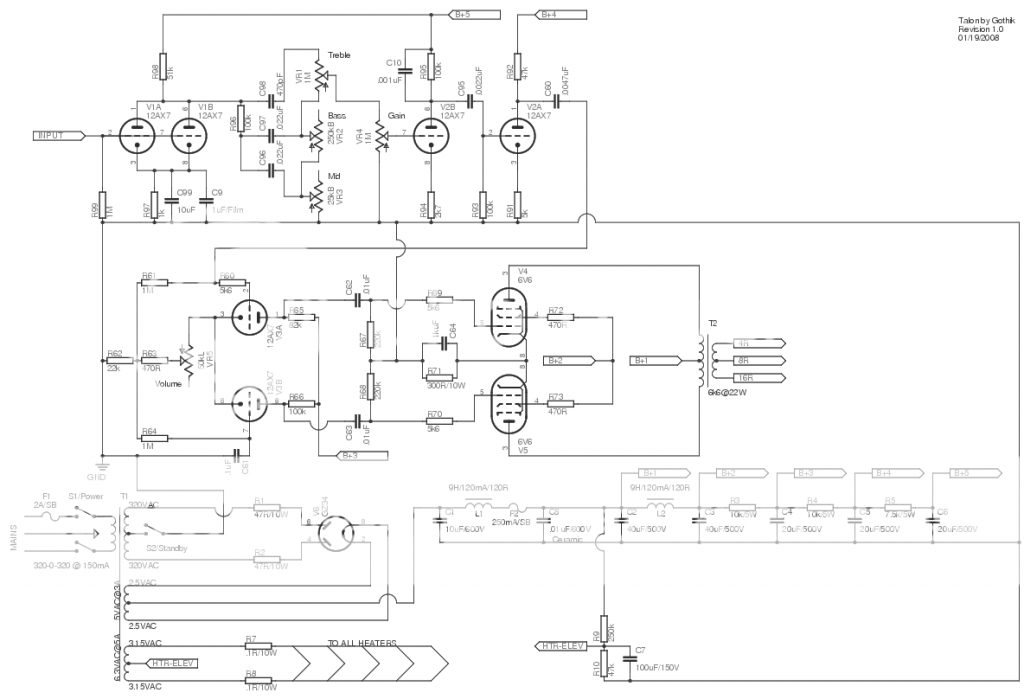
-
iknowjohnny
- Posts: 1070
- Joined: Thu Apr 24, 2008 2:10 am
- Location: los angeles
Re: two voltage dividers one after another?
I didn't realize you could do that without changing the bias to a degree that wouldn't be good. I don't care about driving the power section into OD since i never use it for anything more than small stage volume. But I will definitely try that today, thanks.
-
martin manning
- Posts: 14308
- Joined: Sun Jul 06, 2008 12:43 am
- Location: 39°06' N 84°30' W
Re: two voltage dividers one after another?
It's the load that this NW puts on the stage driving it we are talking about... that is what matters. In my sketch it's 1M exactly as before. If you go to 1M-1M the load goes to 1.5M, and you will get -9.6dB, but also shift the -3dB point down 1/2 octave.iknowjohnny wrote:Ok, yes, thats what i have tried and it does change the tone because it halfs the load. let me just ask this....if i did what I first suggested, will that also half the load? The load part of a set VD is also 1M to ground, but it's separated from the pot's load unless the pot is maxed. Come to think of it, it may not be that your method changed the tone but just didn't cut gain much. In fact i'm pretty sure thats why i dropped that idea.
In any case, what are the possible repercussions of doing what i suggested?
-
iknowjohnny
- Posts: 1070
- Joined: Thu Apr 24, 2008 2:10 am
- Location: los angeles
Re: two voltage dividers one after another?
I guess i am using the word load wrongly, but i always figured that mean resistance to ground. Anyways, i will try that again today also.
EDIT: I see what you mean now.
EDIT: I see what you mean now.
-
martin manning
- Posts: 14308
- Joined: Sun Jul 06, 2008 12:43 am
- Location: 39°06' N 84°30' W
Re: two voltage dividers one after another?
There is also the HF roll-off due to Miller capacitance in the following stage, and at full volume that will now (with 470k-1M) be the same as it was before when the pot was on 7 (50% of it's resistance). If there is a bright cap involved then its connection to the top of the pot would have to be relocated to the far side of the 470k.
-
iknowjohnny
- Posts: 1070
- Joined: Thu Apr 24, 2008 2:10 am
- Location: los angeles
Re: two voltage dividers one after another?
No bright cap, but thats good to know. I've messed with the gain pot like this too and never thought about that. It has a cap.
Re: two voltage dividers one after another?
There's two types of load in an amp, DC load and AC load. AC load is the load that we're more concerned with when we're talking about signal attenuation (in terms of the signal being AC-coupled between stages*)iknowjohnny wrote:I guess i am using the word load wrongly, but i always figured that mean resistance to ground. Anyways, i will try that again today also.
EDIT: I see what you mean now.
'AC load' is formed by the extent to which AC is attenuated when there is a current path between the AC signal and a 'DC-like state'. A high-resistance (low current) path has a relatively lower AC load than a low-resistance (high current) path.
A 'DC-like state' occurs both within the ground return, and within the DC power supply (HT/B+) rail. (Remember that the filter caps are shunting any AC that in the power rail, to the ground return, so the power rail and the ground return 'look' one and the same to AC). So any signal coming off a plate experiences AC load from both of those directions - i.e.; through the plate resistor (to the DC power supply), as well as back through the internal plate resistance of the tube and through the cathode resistance (where a cathode resistor is used the AC may be bypassed or unbypassed) to ground, and also through any voltage divider (including volume pot etc) to ground following the stage. All of these things will be acting to attenuate the signal (i.e. anywhere there is a current path to the DC-like state). So the AC signal is wiggling away between these two 'walls' of DC 'no-signalness'. And as long as the current path to the DC-like state has some resistance in it, the AC will keep wiggling in the signal path.
In terms of a voltage divider to ground after the stage, where the resistance is in series with the plate of the previous stage and the grid of the following stage, this resistance interacts with the miller capacitance of the following stage to roll off HF. You can get around this by bypassing the series resistance with a cap
* You can also have DC-coupling but I did't want to get too far off the topic.
He who dies with the most tubes... wins