
I've made up my mind to only use round power inlets and fuses on chassis from now on.
Today I spent about half an an hour using a Dremel rotary tool with a fiber cutting wheel to cut out an IEC inlet connector with built-in fuse. (It would be more accurate to say I used 3 cutting wheels, because the first 2 came apart).
Never again.
I hate cutting IEC connectors on chassis
Moderators: pompeiisneaks, Colossal
-
gingertube
- Posts: 531
- Joined: Mon Nov 14, 2011 2:29 am
- Location: Adelaide, South Oz
Re: I hate cutting IEC connectors on chassis
Adel Nibbler Tool and a file work well but I agree that cutting holes for IEC sockets is a PITA.
They make chassis punches for valve socket holes whty can't we have one for IEC sockets?
Cheers,
Ian
They make chassis punches for valve socket holes whty can't we have one for IEC sockets?
Cheers,
Ian
Re: I hate cutting IEC connectors on chassis
They do make such a thing. They're expensive but ...
Sometimes come up on fleabay.
I know this.

Sometimes come up on fleabay.
I know this.
Why Aye Man
Re: I hate cutting IEC connectors on chassis
There is at least one IEC punch, it's not cheap.
I did run across a used Greenlee rectangle punch that should have be ideal for IEC. They wanted $50 as opening bid. I didn't prusue it because there was something mistyped on the listing that left some ambiguity (and cash is tight).
I did run across a used Greenlee rectangle punch that should have be ideal for IEC. They wanted $50 as opening bid. I didn't prusue it because there was something mistyped on the listing that left some ambiguity (and cash is tight).

Re: I hate cutting IEC connectors on chassis
Dremel cutting tool and then file to finished size. Yes, about 30 minutes is what it takes me, too. It takes patience and a willingness to do it. I'm not going to spend for a punch. If you do it often enough, then the punch pays for itself. Not when I do one or two a year.
BTW, it takes even longer if you really want to match the outline of the IEC, including rounded corners and some have those funny 45 degree faces integrated into the rectangle.
BTW, it takes even longer if you really want to match the outline of the IEC, including rounded corners and some have those funny 45 degree faces integrated into the rectangle.

Re: I hate cutting IEC connectors on chassis
I don't think of it as a joy, but don't avoid it either. I like having IEC sockets, and the metal IEC sockets I bought with EMI filter are the bomb. I drill four 3/8" holes in the corners, and use a jig saw to cut out the shape. Cutting an aluminum chassis with a jig saw is very easy...Dremel is the WRONG tool for the job--I tried it!
Apex Jr had a bunch of these for cheap. Plus, the outer flange covers the ugly hole you've made in the chassis!
[img:960:765]http://img.directindustry.com/images_di ... 388279.jpg[/img]
Apex Jr had a bunch of these for cheap. Plus, the outer flange covers the ugly hole you've made in the chassis!
[img:960:765]http://img.directindustry.com/images_di ... 388279.jpg[/img]
I build and repair tube amps. http://amps.monkeymatic.com

Re: I hate cutting IEC connectors on chassis
Drill + 1/2 round Greenlee punch + Klein nibbler + flat file has made it from an hour long ordeal from hell to a 20 minute ordeal from hell. Wish the nibbler had more leverage, it makes your hands hurt. Why is it so compact? Do electricians keep them in their pockets all day? You also work blind w/ it so you must build up some skill. You don't want to over-nibble - no, no no ,don't over nibble.
Re: I hate cutting IEC connectors on chassis
IEC routing template how to. http://www.silvatone.bravepages.com/Tut ... Cutout.htm
I just do the Dremel and file. A drilled hole in each of the six corners then connect the dots with the Dremel cut-off wheels and file, never had it take very long.
The fiberglass reinforced wheels are suppose to work much bettter then the regular exploding ones but i haven't had chance to test this out since purchasing some.
-
JazzGuitarGimp

- Posts: 2357
- Joined: Mon Jul 23, 2012 4:54 pm
- Location: Northern CA
Re: I hate cutting IEC connectors on chassis
I used to have a few Greenlee punches for DB37 and DB25 connectors. These connectors are held to a stringent specification, so EVERY company that makes them use the exact same dimensions. Not so with IEC connectors. If the companies that made IEC's were smart, they would offer a chassis punch for their connector. Once you've put out the $100 or so dollars for the punch, you're sure to keep buying their connectors...
Lou Rossi Designs
Printed Circuit Design & Layout,
and Schematic Capture
Printed Circuit Design & Layout,
and Schematic Capture
Re: I hate cutting IEC connectors on chassis
I drill the corners and use a jigsaw with a Bosch metal cutting blade. Works very well on aluminum. I use a flat file to finish.
Steve

Re: I hate cutting IEC connectors on chassis
My procedure with the diecast boxes I use for chassis is to drill a chain of small holes just inside the outline of the ultimate cutout. These holes do not need to be particularly accurate, as they will be removed anyway.
[IMG:800:600]http://i497.photobucket.com/albums/rr33 ... 384b72.jpg[/img]
The chain of small holes are enlarged by gently tilting the chassis while the bench drill is spinning. This enlargement removes the material between the holes, until the unwanted central piece of diecast can be easily removed.
[IMG:800:600]http://i497.photobucket.com/albums/rr33 ... f3b3e3.jpg[/img]
With the large hole now open, a file is used to enlarge this hole to its final dimensions. I don't bother with the orientation keys across two of the corners, because I usually manage to install my IEC connectors the correct way. But not always.
[IMG:800:600]http://i497.photobucket.com/albums/rr33 ... 3a9193.jpg[/img]
This method is rather labor intensive, but with both diecast and sheet aluminium is quite simple to do with minimal tools. I've tried using a Dremel, but it took a frustratingly long time.
Re: I hate cutting IEC connectors on chassis
I'm particularly bad at drilling the corners to match the profile of the IEC. What size bit do you use? And then, somehow, I have a tendency to end up outside the cutting line instead of tangent to it. Any hints on controlling this using a hand drill? I have a good pointy punch, but I guess I'm not centering it properly.
If you are going to drill and file or Dremel and file, a step bit will give you a nice 3/4" hole to start with. From there you can either file it to final size or use the Dremel and then file it. The step bit removes a lot of material quickly.
I've seen pictures of a router jig for use on aluminum. Steel is too hard for a router. Opps, I see davent covered the router jig.
Re: I hate cutting IEC connectors on chassis
oh man darryl i'm so glad you posted that picture! i'm definitely gonna give that a go next time. i've always been hesitant with the dremel for fear of something flying off. perhaps unwarranted, but i can't get over it.
Re: I hate cutting IEC connectors on chassis
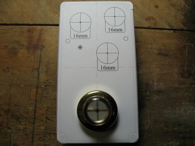
PDF for the layout i use with the Qualtek IEC/fuse sockets i buy. (1/8" or smaller drill bit for the corners.) You can use Inkscape to edit and adjust this as needed.
I center punch all the crosshairs using an optical center punch, then better define them with a spring loaded center punch, to the drill press starting with a 1/16" bit, if the punch dimple is good and well defined a hand drill is no problem to use.
[IMG:800:600]http://i216.photobucket.com/albums/cc30 ... 85758b.jpg[/img]
You do not have the required permissions to view the files attached to this post.
Re: I hate cutting IEC connectors on chassis
The exploding Dremel cut-off wheels go hand-in-hand with a full face shield.kwijabo wrote:oh man darryl i'm so glad you posted that picture! i'm definitely gonna give that a go next time. i've always been hesitant with the dremel for fear of something flying off. perhaps unwarranted, but i can't get over it.