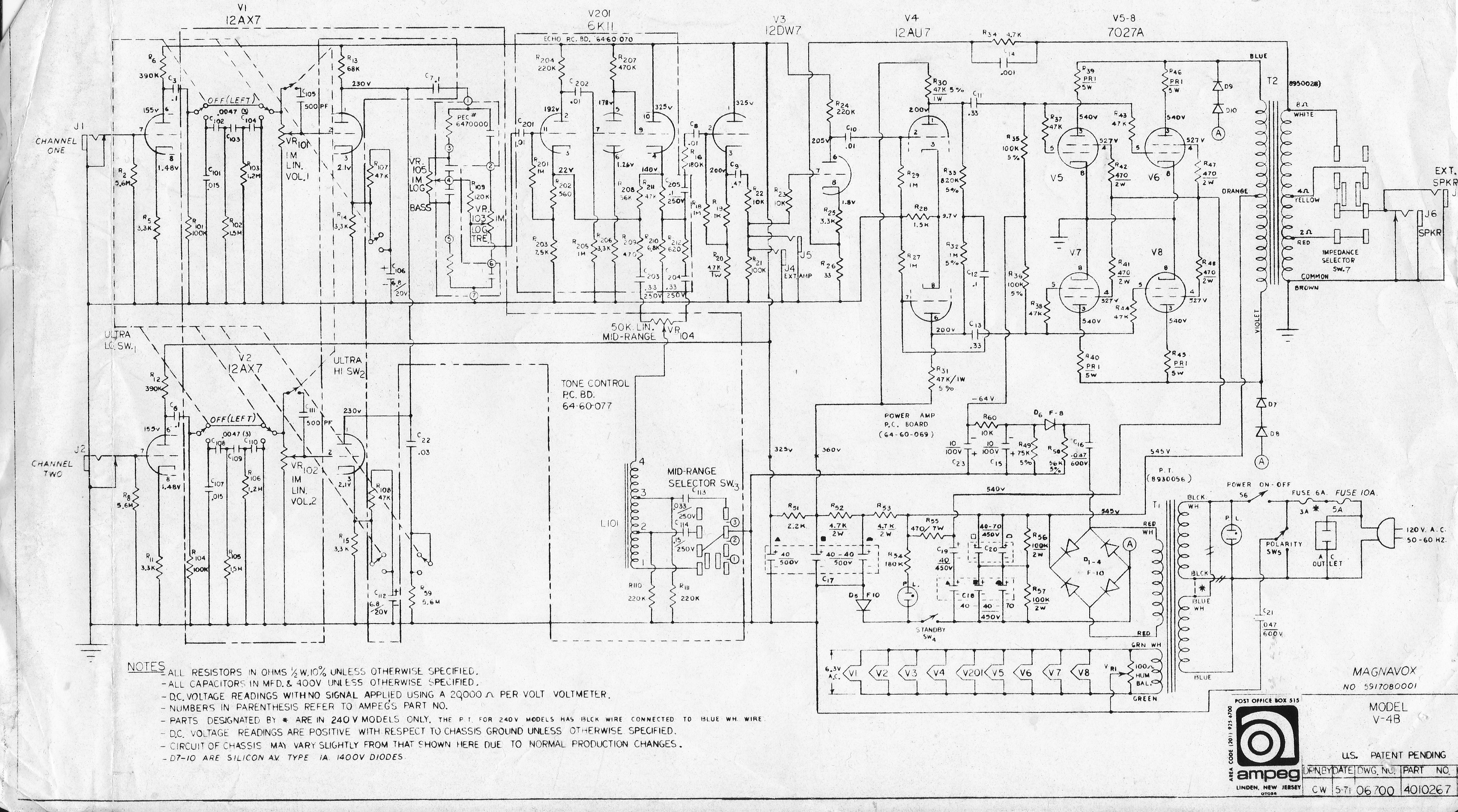
I'm working on a d'lite whose donor iron gave me way too much B+ . I swapped out for the Weber WPTGP http://taweber.powweb.com/store/PTGPsch.jpg , and I've got B+ where I want it, but my fixed bias circuit(express) ain't happening. I'm looking at this scheme : http://www.ampegv4.com/images/schematics/V4B.jpg, and I'd like to make it adjustable, but I'm not sure where to sub my 25K trimpot.
I'm assuming R49,50 will need to tweaked, and the trim would go at R60.
I'll have ~430 plates w/ 6V6.
Any suggestions?
edit I've got 230VAC on top and bottom of bridge
bridge rect + fixed bias
Moderators: pompeiisneaks, Colossal
-
Smokebreak
- Posts: 1391
- Joined: Tue Dec 18, 2012 5:53 pm
- Location: Texas
-
Smokebreak
- Posts: 1391
- Joined: Tue Dec 18, 2012 5:53 pm
- Location: Texas
Re: bridge rect + fixed bias
Well I've got neg voltage now, -55V, but R60 is not the spot for the trimmer. It does nothing there, and I do not understand why.
-
martin manning

- Posts: 14308
- Joined: Sun Jul 06, 2008 12:43 am
- Location: 39°06' N 84°30' W
Re: bridge rect + fixed bias
Here's Marshall's bias supply circuit from JCM900. You can tweak R30 to get where you need to go for the correct bias range. I'm not making sense of your voltages, though. If you want 430VDC, then you will need HT VAC around 430/1.414 = 304.
You do not have the required permissions to view the files attached to this post.
-
Smokebreak
- Posts: 1391
- Joined: Tue Dec 18, 2012 5:53 pm
- Location: Texas
Re: bridge rect + fixed bias
Ok thanks, well I put a trimmer in R50 on the Ampeg scheme, and I've -50 all the way down to 0.
Should I add resistance from trimmer to ground so my bias never has the opportunity to goto 0?
I imagine the voltages may be due to the funky PT I'm using? I just checked again and AC legs are 186V and 212V with respect to ground, and B+ is 440VDC. Between the secondaries is 331VAC though, so somehow I've got a 1.3 multiplier happening..
-
martin manning
- Posts: 14308
- Joined: Sun Jul 06, 2008 12:43 am
- Location: 39°06' N 84°30' W
Re: bridge rect + fixed bias
Measure across the HT leads to get the input voltage to the bridge, so your 331 makes sense, as you will typically only get about 95% of the 1.414 factor. I'd rather not put the trimmer on the high voltage divider, and keep the 56k there to limit the current draw and the voltage across the input cap.
Last edited by martin manning on Fri Sep 20, 2013 11:10 pm, edited 1 time in total.
-
Smokebreak
- Posts: 1391
- Joined: Tue Dec 18, 2012 5:53 pm
- Location: Texas
Re: bridge rect + fixed bias
Ah i didn't even think of that trimmer being right on the HV leg. Thanks a bunch.