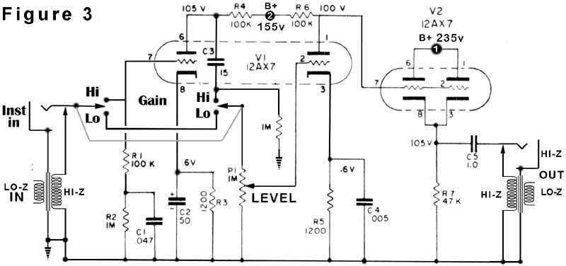
So I'd like to start making plans on a 2 channel preamp based off of an Altec 1566A, a phantom power supply from the same website, and the "famous" $5 preamp. I assume (wrongly?) that it would be fine to Frankenstein all 3 schematics together. Here they are.
The preamp http://www.tangible-technology.com/tube ... tec_3b.jpg
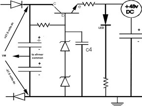
Phantom power http://www.tangible-technology.com/tube ... antom1.JPG
$5 Preamp http://www.record-producer.com/i/5-doll ... ematic.jpg
Basically, the plan would be to mesh the phantom power supply with the $5 preamp, and then have the $5 preamp output go to the "low" input on the Altec 1566A.
Folly?
What would be the problem with combining these 3 schematics?
Moderators: pompeiisneaks, Colossal
-
EtherealWidow
- Posts: 333
- Joined: Sun Jun 10, 2012 8:47 pm
1 others liked this
-
EtherealWidow
- Posts: 333
- Joined: Sun Jun 10, 2012 8:47 pm
Re: What would be the problem with combining these 3 schematics?
Alright. So here's a rough draft of all 3 of them put together.
https://www.dropbox.com/s/n0faarb9vh0cj ... atics.jpeg
Keep in mind that I'm aware that the power supply schematic is not included. That's not what my concern would be. My main concern is making sure that all 3 of these circuits are more or less directly compatible.
Some problems I've seen so far are:
1) I don't know how I'm going to supply the polarized 15V for the op amp and the little diode structures.
2) The cap in the phantom power supply (below the node that says +48V) seems redundant with the other cap going from the +48V node to ground in the $5 preamp schematic.
3) Are the "floating" windings of the transformers in the Altec preamp supposed to remain "floating"?
BTW, I realized that the phantom power supply schematic didn't have any values listed to the components, so here's the source site. If you scroll down a little he has the parts list.
http://www.tangible-technology.com/tube ... rying.html
Last edited by EtherealWidow on Fri May 24, 2013 12:22 am, edited 1 time in total.
-
gingertube
- Posts: 531
- Joined: Mon Nov 14, 2011 2:29 am
- Location: Adelaide, South Oz
Re: What would be the problem with combining these 3 schematics?
I assume you want a microphone preamp.
Here is one I posted to another forum for design review / comment - the comment I got back was "loose the impedance switch and associated resistors".
Cheers,
Ian
Here is one I posted to another forum for design review / comment - the comment I got back was "loose the impedance switch and associated resistors".
Cheers,
Ian
You do not have the required permissions to view the files attached to this post.
-
EtherealWidow
- Posts: 333
- Joined: Sun Jun 10, 2012 8:47 pm
Re: What would be the problem with combining these 3 schematics?
Ah yes. The tube preamp is based off an Altec1566A which, from what I understand, was used in stores for an address system. This version was modified by some guy into a tube DI box/unbalanced preamp. He mentioned using it for microphones and posted the phantom power schematic that I posted, but didn't actually post a schematic of a preamp to use with it, so I just chose the $5 preamp because I was considering it before. Basically what I'm looking to make is a decent tube mic preamp and DI box. Just need to figure out how to best marry all 3 circuits.
-
EtherealWidow
- Posts: 333
- Joined: Sun Jun 10, 2012 8:47 pm
Re: What would be the problem with combining these 3 schematics?
And thank you for the upload of your schematic. Looks pretty good. I'll need to study that and figure out what kind of pad I want and where to put it. Why did they tell you to lose the impedance switch?
-
gingertube
- Posts: 531
- Joined: Mon Nov 14, 2011 2:29 am
- Location: Adelaide, South Oz
Re: What would be the problem with combining these 3 schematics?
I assume because in view of most modern microphone impedances it isn't really required.
Cheers,
Ian
Cheers,
Ian
-
EtherealWidow
- Posts: 333
- Joined: Sun Jun 10, 2012 8:47 pm
Re: What would be the problem with combining these 3 schematics?
Hey! Thanks for responding again. I've been talking to the guy for a couple of days now who modified these Altec 1566A schematics. The main reason I wanted to add the $5 preamp is because I needed a way to get the balanced signal to this preamp, which only shows unbalanced. Turns out, a simple microphone input transformer will fix that...
Hoooo... that's embarrassing. Learn something new every day.
Basically, I'm thinking something along the lines of this thing.
http://www.soundonsound.com/uploads/838937-reamp3.jpg
Sure, the schematic is originally intended for a reamp box, but it basically does what I need. Now the only thing left to be desired is a balanced OUTPUT! How would I go about doing that? Just reversing the schematic?
-
gingertube
- Posts: 531
- Joined: Mon Nov 14, 2011 2:29 am
- Location: Adelaide, South Oz
Re: What would be the problem with combining these 3 schematics?
Now I'm a bit out of my comfort zone with respect to knowledge of microphone circuits so you might like to check this with someone else.
Dynamic Mics (Sure SM58 and similar) are low impedance, approx 150 Ohms
Condenser Mics (Sure SM86 and similar) are higher impedance, typically greater than 600 Ohms and require phantom power.
If you are simply trying to get a balanced input then your circuit of above is probably OK.
If you are trying to match impedances as well then you will want a step up transformer like the Jensen in my design. It steps up the voltage by X10 and steps up the impedance by X100 (10 squared).
I would go to the Jensen Website and look at some of their typical ciruits.
http://www.jensen-transformers.com/mic_in.html
See the Applications - Schematics pages
Cheers,
Ian
-
EtherealWidow
- Posts: 333
- Joined: Sun Jun 10, 2012 8:47 pm
Re: What would be the problem with combining these 3 schematics?
I'll have to look into an impedance matching circuit. I like dorky versatility and I won't have to pay $300 for a Cloudlifter CL-Z.
Found my schematic for the unbalanced to balanced out!
http://www.jensen-transformers.com/as/as052.pdf
Going to have to ask them what to do if I'm planning on using a TS cable for the input, rather than a TRS.
Now I just have to save up $300 for all the iron I'll need. Goody.
Found my schematic for the unbalanced to balanced out!
http://www.jensen-transformers.com/as/as052.pdf
Going to have to ask them what to do if I'm planning on using a TS cable for the input, rather than a TRS.
Now I just have to save up $300 for all the iron I'll need. Goody.