Last week I successfully installed my first VVR3 in a Tweed Champ with all of your help and guidance! I am very good at following directions (20 years of being trained by wife), but now lack the skills of being able to think on my own
After jamming with my tweed champ, my buddy asked me to install a VVR3 for him as well. He wanted to control attenuation of the whole amp, which is Cathode biased. I was looking over the wiring layout (attached) to see where the VVR3 would connect.
Just wanted to double check my thinking before I even consider opening the back up.
The 5E3 Tweed Deluxe has a standby switch which my 5F1 champ did not. Does the VVR3 just connect right through this feed before it gets to the first filter cap?
bretschwartz wrote:Does the VVR3 just connect right through this feed before it gets to the first filter cap?
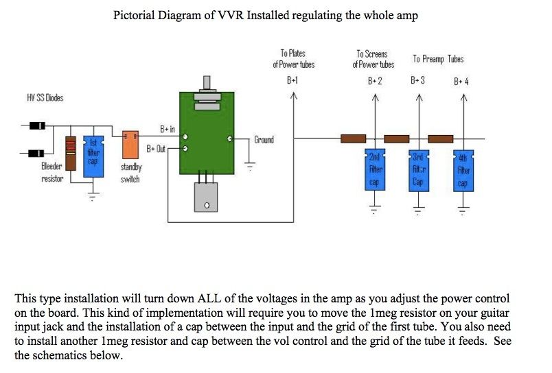
I think that the VVR would best be located after the first cap, before the plates and the rest of the power chain. This way, the regulator doesn't have to deal with the huge ripple current pulses coming out of the rectifier.
I installed mine between the first power supply cap and the dropping resistor. As Mark stated. So I kinda used the first cap as a smoothing filter. I bolted the FET directly to the chassis and it failed within a few days. I then added a heatsink to the outside of the chassis at the FET mounting bolt. The heatsink is something like this: http://www.mouser.com/MobileCatalog.aspx?page=2114
vibratoking wrote:I installed mine between the first power supply cap and the dropping resistor. As Mark stated. So I kinda used the first cap as a smoothing filter. I bolted the FET directly to the chassis and it failed within a few days. I then added a heatsink to the outside of the chassis at the FET mounting bolt. The heatsink is something like this: http://www.mouser.com/MobileCatalog.aspx?page=2114
Been fine ever since.
thanks for the info on the heat sink, i'll check it out. I figured my wiring diagram wouldn't be that easy. Is this diagram correct? [/img]
It looks like you're getting plenty of good advice as to how to wire the VVR into the circuit. So I thought I'd address a different subject: When I installed a VVR into my Tweed Deluxe clone, I removed the standby switch and mounted the VVR pot in the hole that used to be for the standby switch. The 5E3 panel is pretty cramped, so adding a hole for the VVR will be tricky at best. You can get a shoulder washer that adapts the 1/2" hole down to the needed 3/8" hole for the pot. After having read most of Merlin's power supply book, I am now with the understanding that a standby switch is completely unnecessary in terms of tube health, but I tend to turn the VVR all the way down when I do a cold start - what can I say? Old habits die hard!
Lou brings up a good point. I mounted my VVR pot in the extra speaker jack on the back. This allowed me short wires and a convenient spot close to the pot to mount the FET and heatsink. The downside is that the pot is not convenient to access through the back panel, but my chassis is horizontally mounted in a head type case. The access is OK for me since I don't really need to access the pot that often. Once or twice per gig to find the setting that is right for the night.
It looks like you're getting plenty of good advice as to how to wire the VVR into the circuit. So I thought I'd address a different subject: When I installed a VVR into my Tweed Deluxe clone, I removed the standby switch and mounted the VVR pot in the hole that used to be for the standby switch. The 5E3 panel is pretty cramped, so adding a hole for the VVR will be tricky at best. You can get a shoulder washer that adapts the 1/2" hole down to the needed 3/8" hole for the pot. After having read most of Merlin's power supply book, I am now with the understanding that a standby switch is completely unnecessary in terms of tube health, but I tend to turn the VVR all the way down when I do a cold start - what can I say? Old habits die hard!
All the best,
Lou
Lou,
Would it be too much to ask to post or PM some pics of your tweed deluxe? I want to see your VVR installed in chassis and where exactly you made your connections.
Regarding the physical VVR location, I have not thought about that yet, I will probably take your advice. On the Champ I just built, I installed the VVR into the existing fuse location and reinstalled fuse out the bottom of the chassis.
thanks for all the thoughtful info!!!
Hi Bret,
Yes, I should be able to get to this in the next day or so.
It looks like you're getting plenty of good advice as to how to wire the VVR into the circuit. So I thought I'd address a different subject: When I installed a VVR into my Tweed Deluxe clone, I removed the standby switch and mounted the VVR pot in the hole that used to be for the standby switch. The 5E3 panel is pretty cramped, so adding a hole for the VVR will be tricky at best. You can get a shoulder washer that adapts the 1/2" hole down to the needed 3/8" hole for the pot. After having read most of Merlin's power supply book, I am now with the understanding that a standby switch is completely unnecessary in terms of tube health, but I tend to turn the VVR all the way down when I do a cold start - what can I say? Old habits die hard!
All the best,
Lou
Lou,
Would it be too much to ask to post or PM some pics of your tweed deluxe? I want to see your VVR installed in chassis and where exactly you made your connections.
Regarding the physical VVR location, I have not thought about that yet, I will probably take your advice. On the Champ I just built, I installed the VVR into the existing fuse location and reinstalled fuse out the bottom of the chassis.
thanks for all the thoughtful info!!!
Hi Bret,
A few pics attached. The VVR Board is just to the right of the power transformer. You can see the twisted triplet of wires (Yellow, Purple, Green) that go to the VVR pot at the left end of the control panel. The two yellow tubular caps that form a "V" at the right end of the chassis are the ac-coupling caps at the two input stages. I did not install caps for the volume pots - and in my case, they proved unnecessary - no scratchy volume controls.
HTH,
Lou
You do not have the required permissions to view the files attached to this post.
I did not install caps for the volume pots - and in my case, they proved unnecessary - no scratchy volume controls.
Say What? Are you telling us the volume controls are direct-coupled to the preamp tube plates with no coupling caps in between? That's what it soundds like you're saying....
I did not install caps for the volume pots - and in my case, they proved unnecessary - no scratchy volume controls.
Say What? Are you telling us the volume controls are direct-coupled to the preamp tube plates with no coupling caps in between? That's what it soundds like you're saying....
TT
No, no, no! Anode of preceding stage is AC-coupled through a cap to the CW terminal of the volume control - just like it's usually done. It's my understanding that the grid of a preamp tube can develop a DC voltage on it when the anode supply is substantially reduced. This is why it is recommended that the guitar inputs be AC-coupled when you employ a VVR, so DC is not fed back into the guitar. The same thing can happen at the next preamp stage, where the WIPER of the volume pot is normally DC-coupled to the grid. So people recommend AC-coupling the wiper to the grid because DC on any terminal of a volume pot will sound scratchy when adjusted.

 [/img]