Amps indicator light does light up at all.
Bummed, as I am now officially out of my depth.
Moderators: pompeiisneaks, Colossal
Hi Shaun,shaunf wrote:Guys, please help me. I finished wiring up my amp last night, checked everything as best I know how, and tried to power it up just now. Just switching on the On switch (standby still off) with the bulb limiter and the limiter light glows brightly.
Amps indicator light does light up at all.
Bummed, as I am now officially out of my depth.
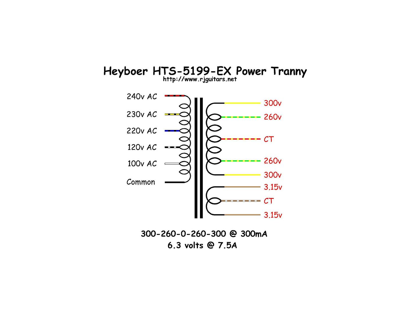
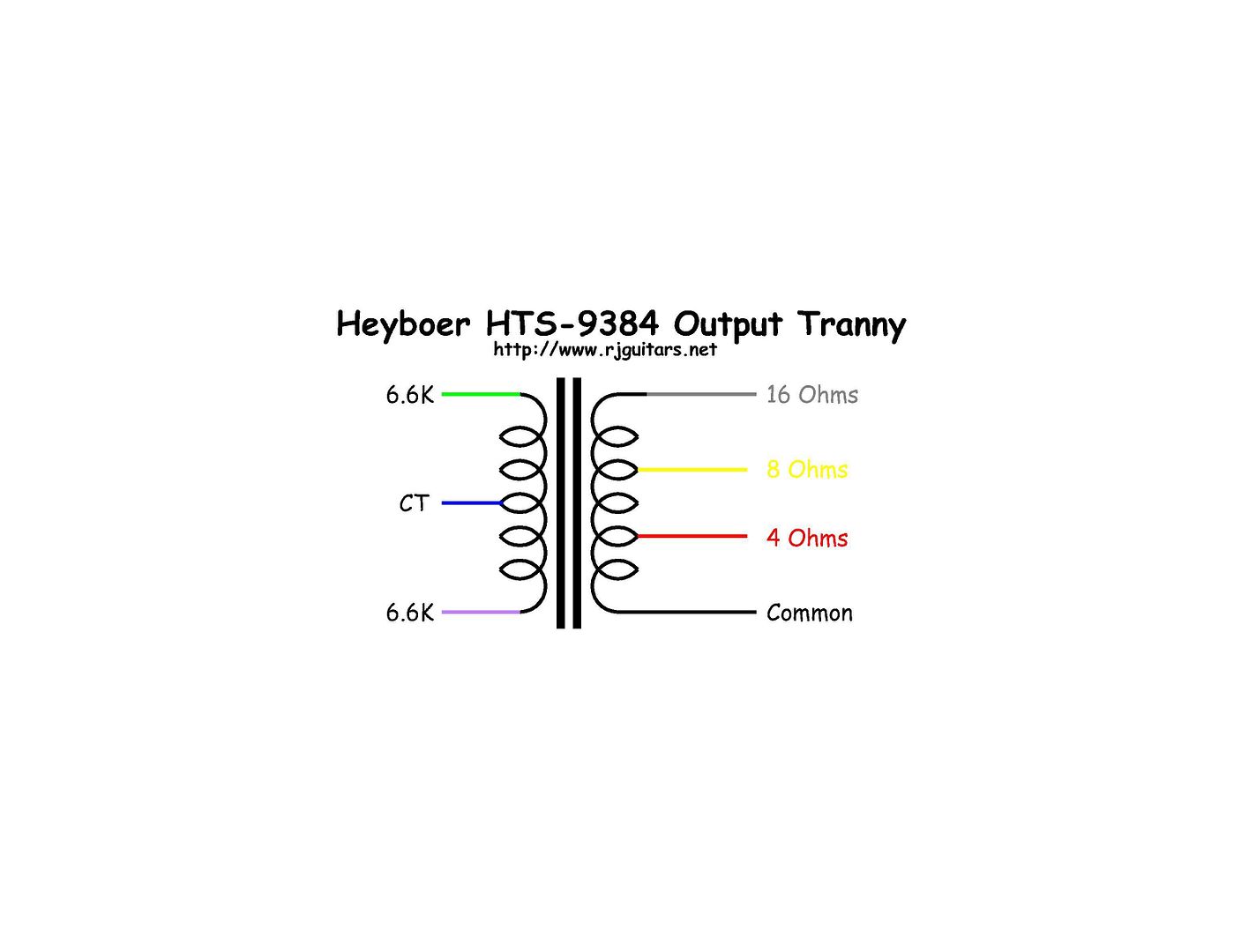
 2383]http://img.photobucket.com/albums/v206/ ... 5199EX.jpg[/img]2383]http://img.photobucket.com/albums/v206/ ... S-9384.jpg[/img]
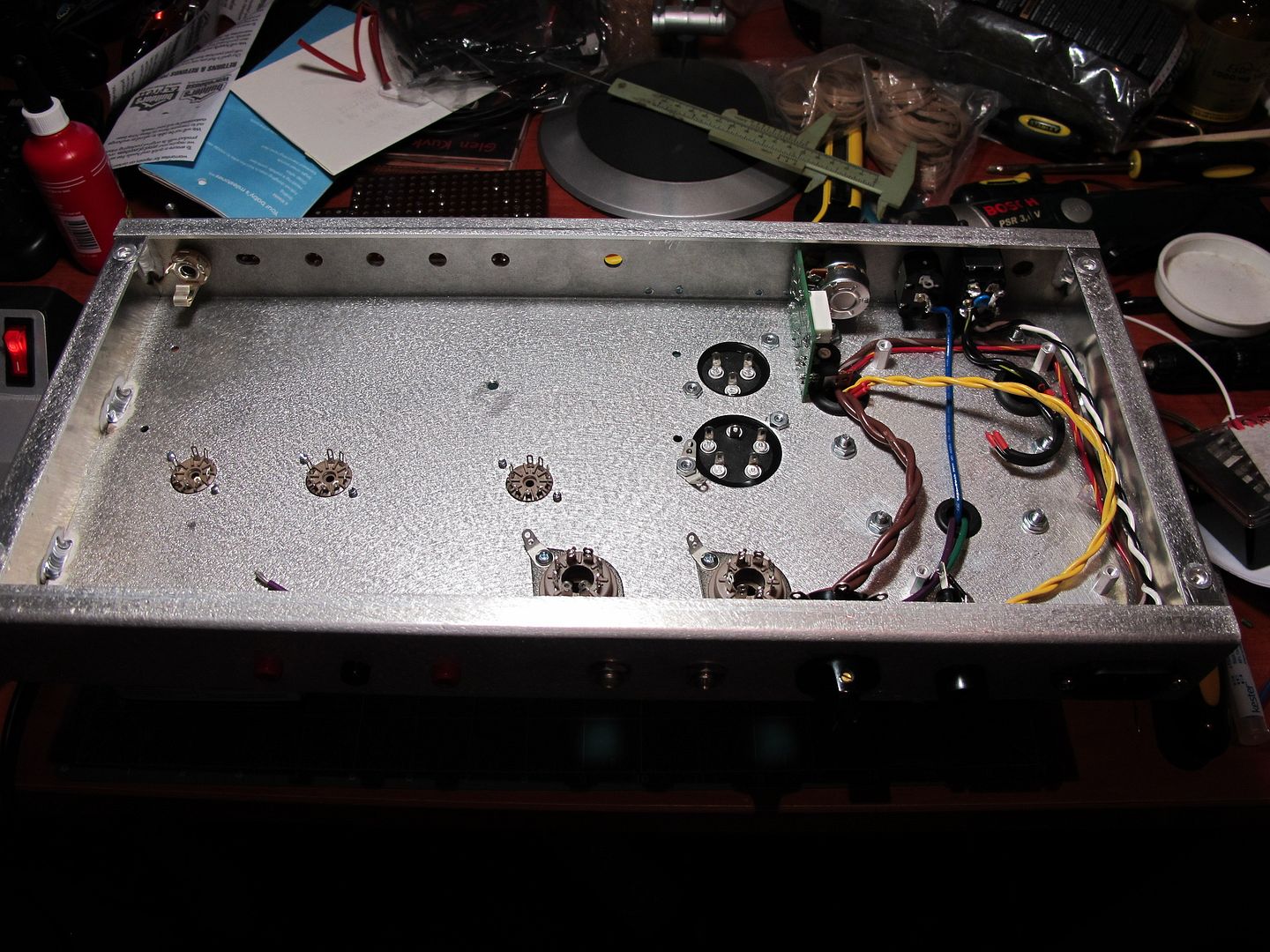
 1665]http://img.photobucket.com/albums/v206/ ... G_1588.jpg[/img]
 1736]http://img.photobucket.com/albums/v206/ ... G_1650.jpg[/img]
 1740]http://img.photobucket.com/albums/v206/ ... G_1651.jpg[/img]
 1980]http://img.photobucket.com/albums/v206/ ... G_1660.jpg[/img]
 1607]http://img.photobucket.com/albums/v206/ ... G_1663.jpg[/img]
 1556]http://img.photobucket.com/albums/v206/ ... G_1670.jpg[/img]
 1542]http://img.photobucket.com/albums/v206/ ... G_1668.jpg[/img]
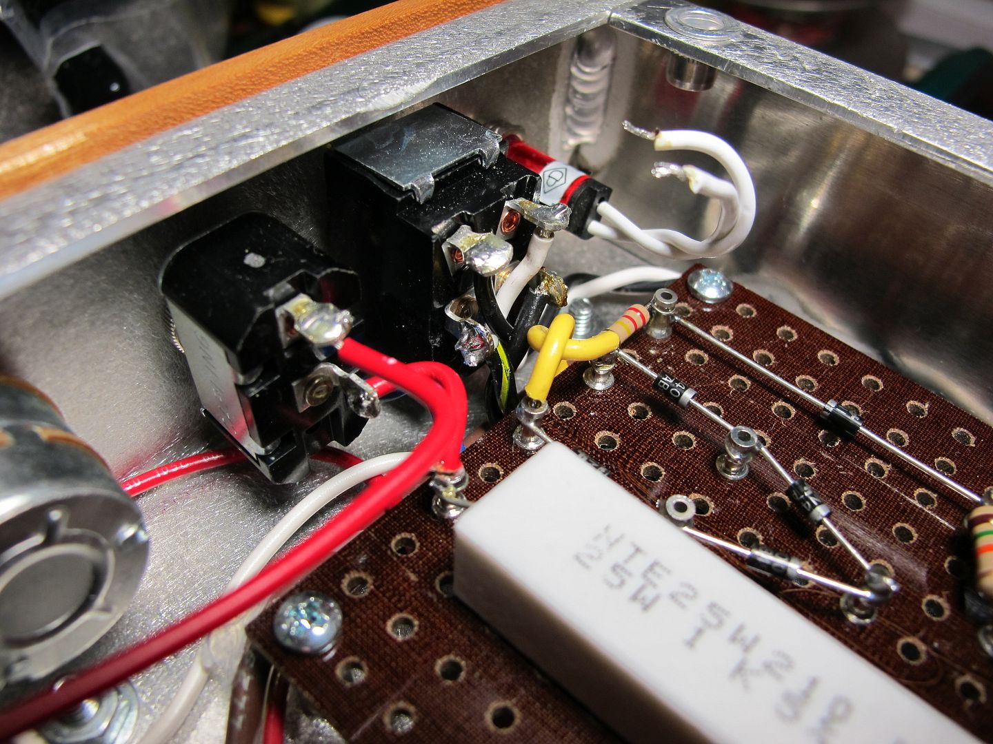
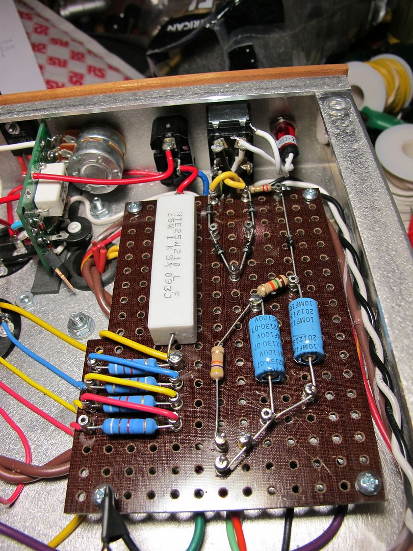
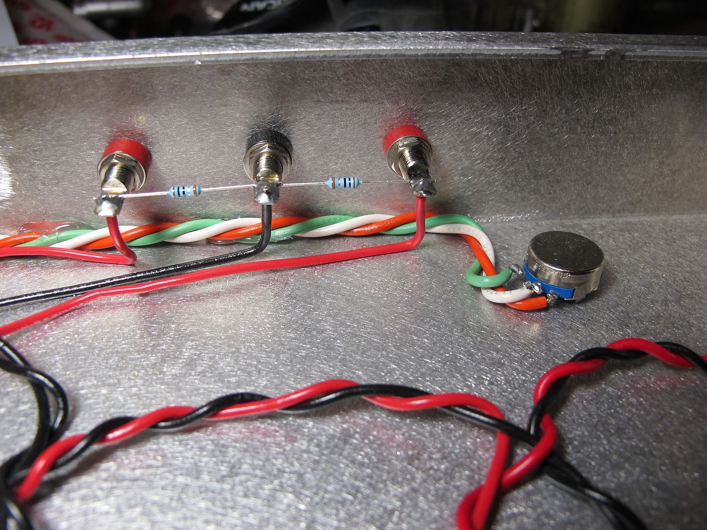
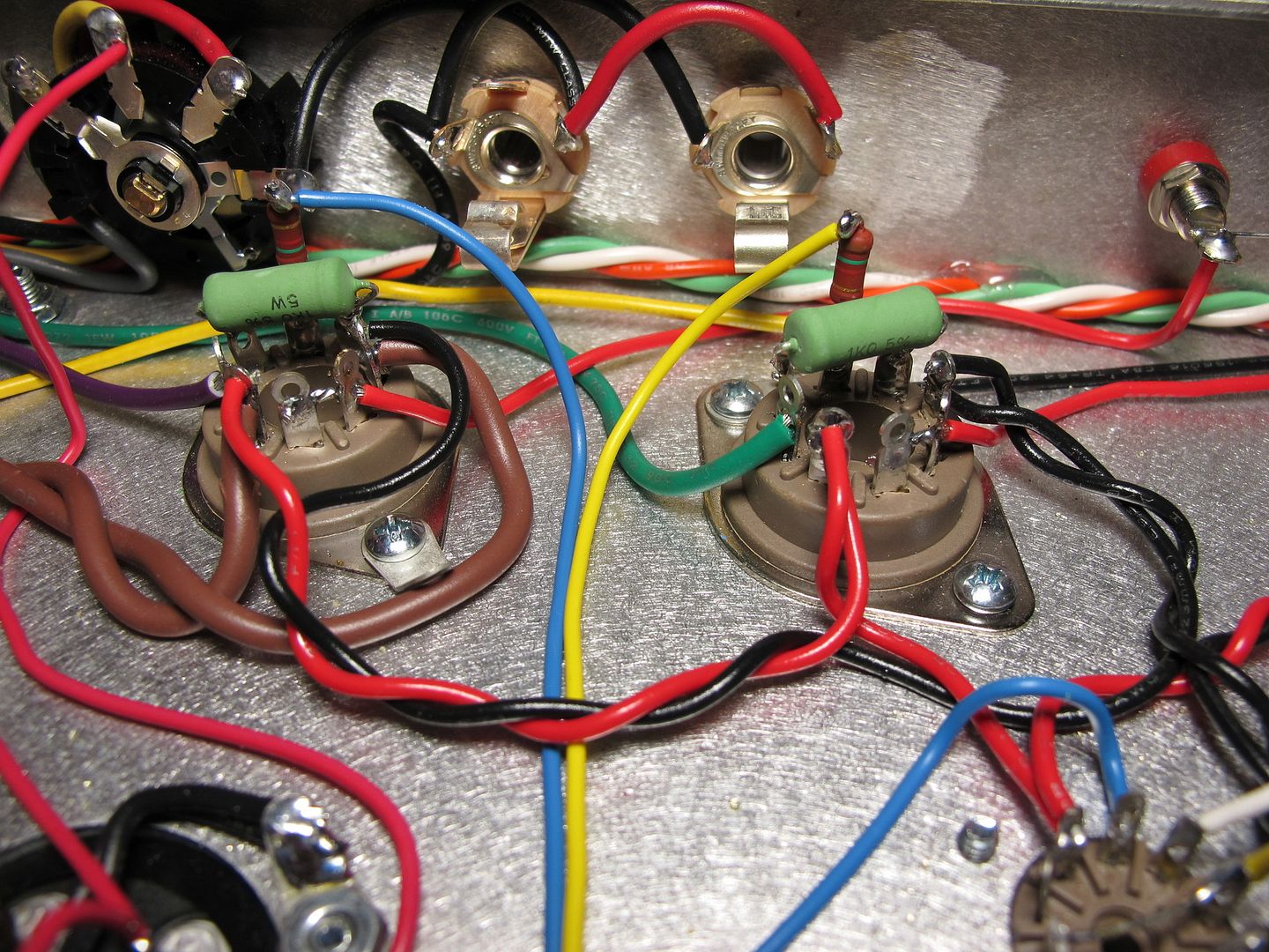
Well dude, you obviously have skills and know what's up (and your amp looks nice) so I hope you didn't take my previous email as derisive. Can you successfully "float" the amp at voltage with all of the tubes removed without the fuse popping? Also, can you measure 120VAC on your power switch, actual rectified DC voltage on your standby switch and heater voltage at 3.3-0-3.3 on the tube socket pins??shaunf wrote:I've been through the PS section of the schematic. From the rectifier diodes, through the main filter caps, up until the Standby switch, I can find no fault in my connections. I'm assuming beyond the standby switch is irrelevant at this point since the problem exists with the standby switch open. The bias circuitry looks fine to me. My external bias pot is simply wired to the 3 turrets the legs of a trimmer pot would normally connect to. White wire connects to pot wiper, and to the turret closest to the 10uf caps, green connects to turret closest to the fuse holder, orange connects to 47k resistor.
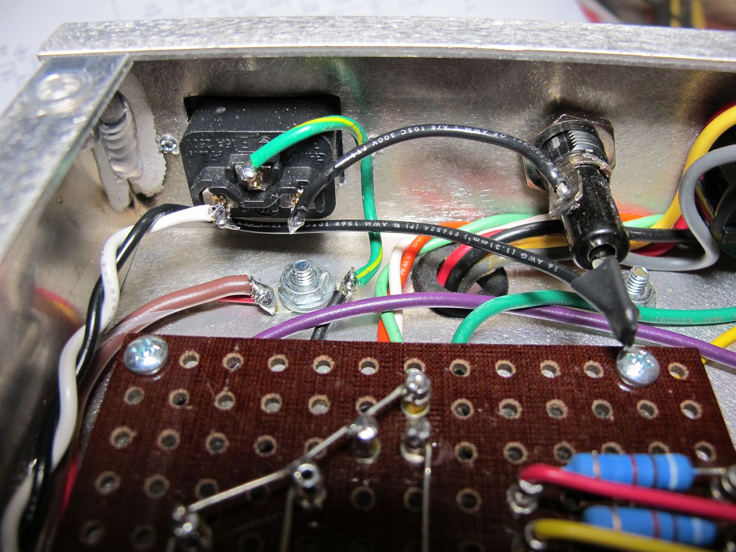
Thanks Dave. There is around a quarter inch of space between the fuse centre pin and the stand off screw so not much chance of touching. Still, I have put a piece of shrink wrap over the centre pin just to be safe.ampgeek wrote:That looks like a nice clean job!
What rotten luck that the center fuse tab lines up dead nuts perfect on the power board stand off screw!
Is it possible that there is contact between those two?
Good luck!
Dave O.
Right on man. I consider myself a beginner as well and am grateful for all the guys that took (and continue to take) the time to endure my questions, many on this board and especially Mhuss in days of yore. One thing about amp failure is that you get a rich opportunity to truly immerse yourself in the why of the amp. The learning curve can be daunting but if you stay cool, troubleshoot in a controlled, linear manner, man, that's a good feeling when you can find the answer to your own problem.shaunf wrote:Hi Colossal,
If I know anything at all about amps, it's only from reading info on places like this. I have very little practical experience at all. This is my first scratch build of an amp. My only other experience comes from a bit of tinkering with my old Marshall.
I am grateful for your post and certainly didn't take offence to anything you said. I am a beginner, and here to learn from those more experienced than I am, and welcome any advice, criticism etc with an open mind. Even just your initial post gave me some structure as to how to begin to go about troubleshooting. When I looked at the schematic and traced my connections, it became clear that the problem had to be limited to a very isolated part of the amp.
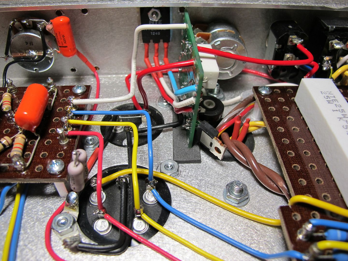
As you have now indicated, it could be related to the VVR. Since removing it simply involves desoldering a couple of wires and reconnecting the standby switch to the primary filter cap, and resoldering the bias voltage wire, I have removed the VVR and retested, and the limiter bulb is glowing at a dull orange colour as expected.
Thanks very much for pointing me in the right direction. I'm going to carry on the startup process now, minus the VVR, and will have to try to pick up why it's causing this shorting problem with Hall Amplification on Monday.
Colossal wrote:Right on man. I consider myself a beginner as well and am grateful for all the guys that took (and continue to take) the time to endure my questions, many on this board and especially Mhuss in days of yore. One thing about amp failure is that you get a rich opportunity to truly immerse yourself in the why of the amp. The learning curve can be daunting but if you stay cool, troubleshoot in a controlled, linear manner, man, that's a good feeling when you can find the answer to your own problem.
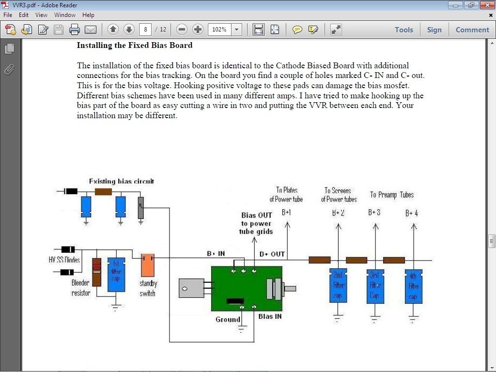
I'm stoked that you can get a dull orange glow with the VVR out of the picture. To remedy this issue, the VVR must be electronically positioned just AFTER the first 80uF cap, but BEFORE the standby switch. The MOSFET needs a current source and at startup, inrush current is high to charge the caps up before the power supply reaches equilibrium. Just move the B+ IN on the VVR board to source that first reservoir cap. Take the B+ OUT on the VVR to Standby. The OT B+1 must also go to the standby switch of course. From there, the OT B+1 and everything else down the rail will see regulated voltage.
 768]http://img.photobucket.com/albums/v206/ ... titled.jpg[/img]
The standby switch is in the same location for the way Dana has drawn it in the installation document you posted as well as on the Express schematic. My guess, but I can't say for sure without studying your photos further is that you had either the VVR upstream of the 80uF cap (attempting to source current directly off the rectifier) or somehow otherwise incorrectly installed. In the way shown in Dana's document, the reservoir cap will fully charge upon powering the amp and then the cap will be immediately available to the VVR and the rest of the amp when the standby is thrown.shaunf wrote:What do you reckon, did I misunderstand this diagram? I must admit, I just saw the Standby switchand just went from there, but now looking at it more closely now that you've opened my eyes, it would seem that the standby switch in the diagram is in a different circuit position to where it is in the Express. Is that right? and is that where I went wrong?
If that's the case shouldn't the VVR B+ in and out be between the standby switch and the 25w resistor on the PS Board, instead of how it is between the multicap can and standby?Colossal wrote:The standby switch is in the same location for the way Dana has drawn it in the installation document you posted as well as on the Express schematic. My guess, but I can't say for sure without studying your photos further is that you had either the VVR upstream of the 80uF cap (attempting to source current directly off the rectifier) or somehow otherwise incorrectly installed. In the way shown in Dana's document, the reservoir cap will fully charge upon powering the amp and then the cap will be immediately available to the VVR and the rest of the amp when the standby is thrown.shaunf wrote:What do you reckon, did I misunderstand this diagram? I must admit, I just saw the Standby switchand just went from there, but now looking at it more closely now that you've opened my eyes, it would seem that the standby switch in the diagram is in a different circuit position to where it is in the Express. Is that right? and is that where I went wrong?

