
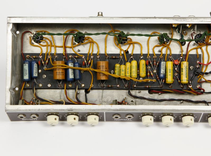
While doing research for my next project I discovered an inaccuracy in a Fender schematic. The schematic and layout for the 6G9 Tremolux indicate that each of the two channels go through a .001 cap to a 220K mixing resistor to the PI. I have found a few indications that the real amp did not have the .001 caps but had a small value cap after the 220K miking resistors. See picture below.
[IMG:799:590]http://i82.photobucket.com/albums/j250/ ... 36ba43.jpg[/img]
What is the result of moving the coupling cap after the mixing resistors. and what value do you think the coupling cap is that is after the mixing resistors?
The schematic is attached below
6G9 Tremolux Questions
Moderators: pompeiisneaks, Colossal
6G9 Tremolux Questions
You do not have the required permissions to view the files attached to this post.
Re: 6G9 Tremolux Questions
probably saving a cap. Instead of two, one on each leg before, change to one after
Re: 6G9 Tremolux Questions
Any tonal impact??
Re: 6G9 Tremolux Questions
Interesting! This is just a guess (maybe someone can run a SPICE simulation to see for sure), but the channel mixing resistors in Fenders provide a parallel path to the AC ground (the filter cap anode) that attenuates the signal. By putting the .001 caps where they are in the 6G9 circuit, the attenuation would be limited to the upper registers so the amp would likely be darker (I wish we could see the value of the input cap to the PI). If you look closely at the pic you posted, you'll also see that the feedback resistor is 56K (the 6G9A/B value, but still working against a 1K5 load resistor), so the feedback was reduced by half, presumably to restore some of the gain lost by the mix resistor attenuation. There may be other transitional elements present, but these would likely be cap values and we can't tell from the pic. The circuit board itself is clearly the 6G9 type and the eyelets where the .001s would have been look like they have been soldered, so the change was likely a factory tweak, or even a Service Bulletin fix.
Re: 6G9 Tremolux Questions
On the other hand the 6G9B schematic is as you describejon wrote:While doing research for my next project I discovered an inaccuracy in a Fender schematic. The schematic and layout for the 6G9 Tremolux indicate that each of the two channels go through a .001 cap to a 220K mixing resistor to the PI. I have found a few indications that the real amp did not have the .001 caps but had a small value cap after the 220K miking resistors.
He who dies with the most tubes... wins