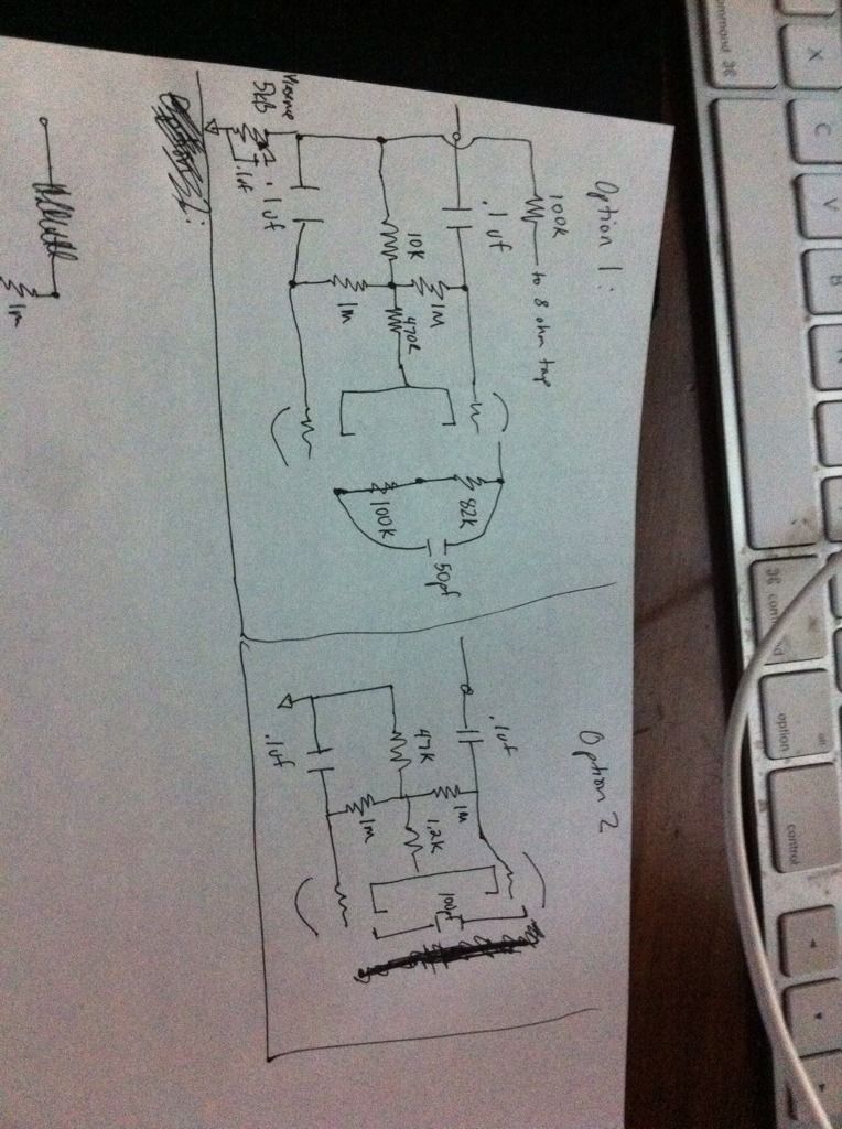
looking at the following two schematics, can someone tell me what the difference would be. if i took a current amp that was built with option 2 and changed it to option 1, what could i expect. assume the voltages are the same and the preamp is that same.
[img:764:1024]http://img.photobucket.com/albums/v217/ ... 56bf90.jpg[/img]
to give a little background as to what i'm trying to accomplish..... i have a pair of express transformers. i'm hoping to build an amp that hasn't been built before. but i don't have the knowledge to do it from the ground up, so I'm trying to understand the differences in sound of certain parts of an amp to decide on what to smash together and how much fine tuning will be required. with the express transformer having 260v and 300v taps, 5v taps, and the OT having dual primaries, i hope to have something that can use all or none of it in one way or another. would really be cool to do a hi/low voltage. solid state/tube rectified amp.
can someone give me a phase inverter tutorial
Moderators: pompeiisneaks, Colossal
Re: can someone give me a phase inverter tutorial
forgot to draw it. the 82k and 100k resistors are in both amps from the B+
-
David Root

- Posts: 3540
- Joined: Fri Aug 04, 2006 3:00 pm
- Location: Chilliwack BC
Re: can someone give me a phase inverter tutorial
Option 1 is a Marshall PI with a presence control and negative feedback from the OT secondary, again standard Marshall.
Option 2 has a bigger tail resistor, 47K, so will balance the dc voltages on the two triode plates better, at least in theory. Lowering the 100K plate resistor to about 95K should help realize that.The cathode resistor is much bigger too. The cathode voltage will be a lot higher. There is no negative feedback from the OT secondary which will sort of offset the cleanness of the better balanced PI a bit.
Option 2 has a bigger tail resistor, 47K, so will balance the dc voltages on the two triode plates better, at least in theory. Lowering the 100K plate resistor to about 95K should help realize that.The cathode resistor is much bigger too. The cathode voltage will be a lot higher. There is no negative feedback from the OT secondary which will sort of offset the cleanness of the better balanced PI a bit.
-
rock_mumbles
- Posts: 244
- Joined: Mon Nov 17, 2008 2:03 am
- Location: Podunk, Idaho
- Contact:
Re: can someone give me a phase inverter tutorial
Option 1 is a Marshall/Express like PI designed to drive EL34's or other larger output octal tubes.
Option 2 is a Vox/Liverpool/Rocket like PI designed to drive EL84's.
There will be a lot more PI signal (to drive the output section) from Option 1.
I have an amp that used the Option 1 PI in a fixed bias 2xEL84 amp it was unusable with the Master volume above half, it was OK with the Master at about 9:00 o'clock ... it was a preamp distortion amp. I quickly converted to the Option 2 PI and the amp sounded a lot better (to me).
Last edited by rock_mumbles on Mon Jun 04, 2012 2:36 am, edited 1 time in total.
Re: can someone give me a phase inverter tutorial
I guess it may have helped if I said option 1 was from the express and 2 from the z28
-
Super_Reverb

- Posts: 188
- Joined: Tue Dec 21, 2010 6:28 am
- Location: Indianapolis, USA
Re: can someone give me a phase inverter tutorial
To help you understand the circuit, think of the PI as a differential amplifier. Given that both tubes in the amp have the same cathode voltage, the amplifier steers the shared bias current between the triode pair based on the relative grid voltage. The signal from the previous gain stage drives the (+) input and when negative feedback is employed, it is connected to the (-) input.
The resistors used in the FB network essentially set the (closed loop) voltage gain. So when you adjust the amount of feedback in this system, you aren't changing the open loop gain, but are actually feeding a back a larger or smaller amount of the output voltage back to the (-) input of the differential amp (PI).
When the PI is used without feedback, the (-) input is set to AC ground via a capacitor.
The resistor between the 1M Ohm tap and the grids (470R -1200R) sets the bias current (remember there are two triodes biased with this resistor, so if you want the feel of a 1.5K Rk, use 750 or 820) and the large resistor beneath that (10-47K) affects balance as David stated. The larger the tail resistor, the better the differential amp is, BUT it is eating up voltage headroom for the plate signal. So there is a tradeoff. Suggest you experiment to find out which values you prefer.
cheers,
rob
Re: can someone give me a phase inverter tutorial
thanks.
so does balancing the voltages with a higher value tail resistor have a cleaner output? and upping the cathode voltage increases headroom of the tube as well?
since the z28 has the cleaner setup of PI, would it be wise to assume that changing to express values will be overkill in the gain area?
so does balancing the voltages with a higher value tail resistor have a cleaner output? and upping the cathode voltage increases headroom of the tube as well?
since the z28 has the cleaner setup of PI, would it be wise to assume that changing to express values will be overkill in the gain area?
Re: can someone give me a phase inverter tutorial
Increasing the tail resistor improves the balance of the input stage and the non-inverting stage. 47k in the tail should allow you to put the same value (say 100k) plate resistors on both stages (where you have used a 12AX7). However it comes at the expense of gain, because the plate-to-cathode voltage is decreased (all other things being equal) with a bigger tail resistance.
There are some other ways (instead of using a tail resistance) for improving the constant current supply to an LTP in order to keep as much gain as possible. See here: http://www.freewebs.com/valvewizard/ccs.html
There are some other ways (instead of using a tail resistance) for improving the constant current supply to an LTP in order to keep as much gain as possible. See here: http://www.freewebs.com/valvewizard/ccs.html
He who dies with the most tubes... wins
Re: can someone give me a phase inverter tutorial
thanks for the help guys. it seems i have a ton of reading to do.
what does the value of the .1uf capacitor accomplish. sometimes you see a .22 there as well.
what does the value of the .1uf capacitor accomplish. sometimes you see a .22 there as well.
Re: can someone give me a phase inverter tutorial
I'm interested in this discussion as well, not so much the electrical theory, but how altering the values higher or lower effects the sound and feel of the amp.
For instance, from my own experimenting, I've learned that lowering the grid resistors from 1M to 330K in a fender type amp will make it not quite so stiff and sterile, more rounded yet still clean.
For instance, from my own experimenting, I've learned that lowering the grid resistors from 1M to 330K in a fender type amp will make it not quite so stiff and sterile, more rounded yet still clean.
Re: can someone give me a phase inverter tutorial
In your drawings, you have 2 x .1uF caps. One of these is a coupling cap from the previous gain stage, and it is there to keep DC off the grid of the 1st (inverting) stage in the LTP. The other caps ties the grid of the non-inverting stage to ground at AC, so that you get a 'mirror image' of the inverting stage's plate signal appearing at the non-inverting stage's plate.wsaraceni wrote:what does the value of the .1uf capacitor accomplish. sometimes you see a .22 there as well.
He who dies with the most tubes... wins
Re: can someone give me a phase inverter tutorial
thanks. so would substituting .22 values there have little to no effect except for some added filtering?
Re: can someone give me a phase inverter tutorial
You want to keep the grid of the non-inverting stage grounded with as-big-a-value (de-coupling) cap as practical. I wouldn't go below .1uF there. This is important because the (inverted pair of) signals that are produced at the plates of an LTP are the 'product' of the two sets of signals that occur at its respective grids. If you want the (inverted pair of) signals at the plates to only reflect the signal at the grid of the inverting stage, then you need to completely ground the AC at all frequencies on the non-inverting stage side, because then the 'signal' at the non-inverting side's grid will be a 'flat line' so to speak, and it won't 'colour' the signals at the plates.wsaraceni wrote:thanks. so would substituting .22 values there have little to no effect except for some added filtering?
But the coupling cap on the inverting stage side is a completely different story. Going to .22uF (instead of .1uF) there will help reduce blocking distortion. BF amps that use a 12AT7 tube in the LTP go to 500pF there.
Last edited by tubeswell on Mon Jun 04, 2012 6:41 pm, edited 4 times in total.
He who dies with the most tubes... wins
-
rock_mumbles
- Posts: 244
- Joined: Mon Nov 17, 2008 2:03 am
- Location: Podunk, Idaho
- Contact:
Re: can someone give me a phase inverter tutorial
Those are coupling caps, coupling caps remove the DC component in the signal and only let the AC component of the signal get to the next stage. On every plate, which has high voltage DC on it, you'll have a coupling cap that connects to the next 'stage' in the amp.wsaraceni wrote:thanks. so would substituting .22 values there have little to no effect except for some added filtering?
The coupling cap in conjunction with the grid reference resistor (grid leak or grid load) forms a high pass filter ... it stops low frequencies and lets high frequencies go through.
With the same value grid reference resistor, larger coupling caps shift the high pass filter to lower frequencies, smaller coupling caps shift the high pass filter to a higher frequency ... there is a possibility of having blocking distortion in the following stage with larger coupling caps.
Re: can someone give me a phase inverter tutorial
thanks guys. it's starting to make sense. i wish i paid more attention in my circuits and systems class. (actually i wish i just remembered more)