Power Tubes' total input capacitance - pF to nF

General discussion area for tube amps.

Moderators: pompeiisneaks, Colossal

User avatar
VacuumVoodoo
Posts: 924
Joined: Fri Feb 17, 2006 6:27 pm
Location: Goteborg, Sweden
Contact:

Re: Power Tubes' total input capacitance - pF to nF

Post by VacuumVoodoo »

roberto wrote:Thank you Mario.

VacuumVoodoo, have you tried to substitute grid resistors?
Have you seen all infos I wrote?
Detailed, in focus photos of guts of those amps would be helpful.
I'd like to suggest you leave 2.2k in place and experiment by adding a capacitor directly between grid and ground. Try something like 100pF.

I use anti parasitic resistors on power tubes for their intended purpose: to prevent HF oscillation and limit grid current when overdriven.
In some cases, during prototyping or repairing/servicing other amps than mine, a small change in component value in those, as well as some other, positions would result in change in sound that could not reasonably be attributed to the component in question. In all of these instances the underlying primary cause was parasitic feedback due to, sloppy wiring, especially re signal leads to power tubes control grids, OT cables running too close to low level signals etc. Once sensitive signal routes got replaced with shielded cabling and parasitic coupling neutralized everything behaved as intended.
Shielding can perform double duty: either prevent interference to enter sensitive areas or prevent it from escaping its source.
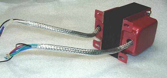
Example of the latter: shielded cabling on output transformer solved an oscillation problem where those leads had to go close to input circuit on the board.
[IMG:556:262]http://i26.photobucket.com/albums/c149/ ... ceened.jpg[/img]
Aleksander Niemand
------------------------
Life's a party but you get invited only once...
affiliation:TUBEWONDER AMPS
Zagray!-review
User avatar
roberto
Posts: 1841
Joined: Tue Nov 27, 2007 4:45 pm
Location: Italy

Re: Power Tubes' total input capacitance - pF to nF

Post by roberto »

VacuumVoodoo, like I said I noticed in all the amps I've tried it on.
The one I built but also Marshall, Mesa, and so on.
Also Marshall uses some grid stopper tricks in different amps,
as I said in my previous posts.

Have you tried different grid stoppers on one of your builds?
User avatar
VacuumVoodoo
Posts: 924
Joined: Fri Feb 17, 2006 6:27 pm
Location: Goteborg, Sweden
Contact:

Re: Power Tubes' total input capacitance - pF to nF

Post by VacuumVoodoo »

Discussing on the web what you can hear or do hear makes no sense and inevitably leads to pie throwing.
If you claim that you hear a significant change (make note I say "change", not "improvement") in upper midrange than it should be fairly easy to demonstrate the effect by measurement and you don't even need a spectrum analyzer.
Just take a series of photos of oscilloscope traces of output waveform when you feed a 600-800Hz square wave into the amp.
One reference trace with no anti parasitic resistors and then traces with different values of resistors.
A good thing to do to avoid inadvertently disturbing tone control knobs is to bypass the tone stack and set presence etc to minimum.
A change in frequency response is clearly visible as change in the shape of what at the input was a square wave.
Ah yes, please use a resistor dummy load instead of loudspeaker. Why? changing loudspeaker position relative to yourself and room orientation WILL change the response.
I also happen to have a pair of these test instruments:

[img:375:500]http://louderandmore.com/images/Auearsdiff.jpg[/img]
Aleksander Niemand
------------------------
Life's a party but you get invited only once...
affiliation:TUBEWONDER AMPS
Zagray!-review
User avatar
roberto
Posts: 1841
Joined: Tue Nov 27, 2007 4:45 pm
Location: Italy

Re: Power Tubes' total input capacitance - pF to nF

Post by roberto »

VacuumVoodoo, instead of denigrating, you can simply say "No, I haven't tryed yet, sorry if i speak with no experience at all on it". :wink:

So, for the second time, stop your flame posts.


If anyone else want to contribute with its own experience, or want to do some tests, I'll be be glad to talk about it.
diagrammatiks
Posts: 558
Joined: Sun Mar 27, 2011 12:28 am

Re: Power Tubes' total input capacitance - pF to nF

Post by diagrammatiks »

Why don't you spice it roberto.

Or better yet buy a scope and log the data yourself.

It can't be that hard to measure out all the stuff you've built.

Are you really going to argue that Alex has never changed out the grid stoppers on his power tubes?
User avatar
VacuumVoodoo
Posts: 924
Joined: Fri Feb 17, 2006 6:27 pm
Location: Goteborg, Sweden
Contact:

Re: Power Tubes' total input capacitance - pF to nF

Post by VacuumVoodoo »

I'm not flaming. You may want to attempt to understand the circuit and the mechanisms involved. Without this, Spice'ing is nothing more than driving blind.
You claim to have observed an effect. I asked you to provide a quantitative illustration and described how to do it.
Whether I experimented with different resistor values or not, and what I observed if I did is irrelevant to current exchange.
As a matter of fact I did observe an effect and already described what really caused it, you chose to ignore my technical analysis and called me flame thrower instead. I'm not putting up with it.
Good luck. You can put your fire extinguisher away.
Last edited by VacuumVoodoo on Fri Apr 13, 2012 8:29 pm, edited 1 time in total.
Aleksander Niemand
------------------------
Life's a party but you get invited only once...
affiliation:TUBEWONDER AMPS
Zagray!-review
User avatar
roberto
Posts: 1841
Joined: Tue Nov 27, 2007 4:45 pm
Location: Italy

Re: Power Tubes' total input capacitance - pF to nF

Post by roberto »

diagrammatiks, are you still rusty for that old post on sloclone forum in which i simulated the 680pF plate resistor's snubber that you said was an RF filter instead of a normal audio filter?

Vacuum Voodoo, I've read your suggestions and appreciate them, Marshall used 20pF on one power tube too for the "comb-like filter" I mentioned.
What I call flames is:
VacuumVoodoo wrote:Perhaps you are a mutant with bat genes?
VacuumVoodoo wrote:Autosuggestion is a powerful trick a mind plays on itself.
VacuumVoodoo wrote:I can hear the grass grow. In winter, under the snow. :wink:
VacuumVoodoo wrote:I also happen to have a pair of these test instruments:
[img:375:500]http://louderandmore.com/images/Auearsdiff.jpg[/img]

Now, back on topic, please.
diagrammatiks
Posts: 558
Joined: Sun Mar 27, 2011 12:28 am

Re: Power Tubes' total input capacitance - pF to nF

Post by diagrammatiks »

VacuumVoodoo wrote:why this double posting?
we'll teach you how to use a computer yet.
diagrammatiks
Posts: 558
Joined: Sun Mar 27, 2011 12:28 am

Re: Power Tubes' total input capacitance - pF to nF

Post by diagrammatiks »

roberto wrote:diagrammatiks, are you still rusty for that old post on sloclone forum in which i simulated the 680pF plate resistor's snubber that you said was an RF filter instead of a normal audio filter?

Vacuum Voodoo, I've read your suggestions and appreciate them, Marshall used 20pF on one power tube too for the "comb-like filter" I mentioned.
What I call flames is:
VacuumVoodoo wrote:Perhaps you are a mutant with bat genes?
VacuumVoodoo wrote:Autosuggestion is a powerful trick a mind plays on itself.
VacuumVoodoo wrote:I can hear the grass grow. In winter, under the snow. :wink:
VacuumVoodoo wrote:I also happen to have a pair of these test instruments:
[img:375:500]http://louderandmore.com/images/Auearsdiff.jpg[/img]

Now, back on topic, please.
Rusty is the word man, especially since your simulation was wrong.

But I'm willing to concede as soon as you show me a scope trace.

I can't fathom why you think it's up to Alex to prove what you hear.

The math doesn't agree with you. If you hear something then show the trace and the guts of the amp your tracing and I'm sure Alex would love to have a discussions with you.

I don't see what could possibly be more civil then that.
User avatar
roberto
Posts: 1841
Joined: Tue Nov 27, 2007 4:45 pm
Location: Italy

Re: Power Tubes' total input capacitance - pF to nF

Post by roberto »

I haven't asked anybody to demostrate what I (and other people too, also in this thread) affirm to notice, neither I can demostrate what happens. I've asked if anybody else has used different grid stoppers and noticed what I (and other people too) have noticed with different grid stoppers on power tubes, and that shouldn't happen.

Also, I've noticed that Marshall often uses different grid stoppers on EL34s, from 4x5k6 to 4x220k to 3x5k6 and 1x10k, to some pF caps on one power tube grid. This fact made me open this thread.

..now can we come back on topic? :roll:
User avatar
roberto
Posts: 1841
Joined: Tue Nov 27, 2007 4:45 pm
Location: Italy

Re: Power Tubes' total input capacitance - pF to nF

Post by roberto »

I'll try to go back on topic.

I was talking about Marshall, take a look here, 5x5k6 grid stoppers:
http://www.ampwares.com/schematics/mars ... 0_100w.pdf

It's not a mistake, 6100 30th 100W heads have 5x5k6 grid stoppers.
gingertube
Posts: 531
Joined: Mon Nov 14, 2011 2:29 am
Location: Adelaide, South Oz

Re: Power Tubes' total input capacitance - pF to nF

Post by gingertube »

Roberto,
I had a think about this - so brainstorming:

1) I can't see that it would be due to grid connduction limiting with the higher value grid stop unless of-course you start considering 47K or more, besides you said that it was noticable at clean settings.

2) I would also think that its not due to a susceptibility to instability with the lower values although that can't be ruled out. The lower grid stop degrades the output tube stability margin AND allows high frequency impulses to kick that tendency to instability.

3) The other thing which can't be ruled out is a bias change with higher grid stop values. Power Tubes have significant grid current, that is why there are different max Rg1 values specified on the data sheets for fixed bias (where there is no self adjustment) and for cathode bias (where there is some self adjustment). I'm not sure of the grid current of a typical 5881 at high voltage but it may be several hundred microamps, enough to drop a couple of volts across the grid leak. I recently measured a 300B grid current at 2mA not that we use 300B for guitar amps of-course.

4) The higher grid stop will also somewhat isolate the grid capacitance of the output tube from loading the driver stage so it may be driver stage effects that you hear.

5) There is one other "off the wall" idea I have. In line with 4) above, that Phase Inverter has a cap placed anode to anode. AC wise that means that there will be a virtual earth (0 signal point) in the middle of that cap which will move about with Phase Inverter output balance. That may be affected by the output tube grid capacitance with low grid stop values. That is, you may have some self balancing at high frequencies with a lower value grid stop. Actually given the size of the capacitances in question this is not so "off the wall" as I originally thought. If it helps to "visualize" this, think of that 100pF between the PI anodes as 2 off 200pF in series with the centre connected to 0V, because of the opposite phase signals at each end of the cap, this is what it looks like from an AC analysis point of view. The say 50pF per tube of grid capacitance then becomes significant and the amount of isolation afforded by the grod stops becomes important.

All of these seem marginal things but I can't think of anything else. Maybe if they all add together you get a noticable change.

Edit: The more I think about it the more I'm convinced that it is 5) above which is working to give you a noticable change with grid stop value.

Cheers,
Ian
User avatar
roberto
Posts: 1841
Joined: Tue Nov 27, 2007 4:45 pm
Location: Italy

Re: Power Tubes' total input capacitance - pF to nF

Post by roberto »

Thank you Ian,
I have 56p across the PI, but your last point make me thought about another aspect I've noticed on some Marshall (both on schematic and real amps): in some Marshall, where they started "grid stopper mods" they put the 47-100pF cap AFTER the two coupling caps.

So, let's summarize anomalies I've seen on some Marshalls:

- one of the grid stopper is doubled, or they are 220k
- PI's pF cap is sometimes after coupling caps
- sometimes there are some 20-100pF caps from grid to ground
Marioverkill
Posts: 61
Joined: Thu Jan 05, 2012 2:23 pm
Location: NB,Canada

Re: Power Tubes' total input capacitance - pF to nF

Post by Marioverkill »

Roberto !

I read some more.According to Richard Kuehnel in Guitar Amplifier Power Amps:The gridstopper affects the Bias excursion.

sending PM

Mario
User avatar
roberto
Posts: 1841
Joined: Tue Nov 27, 2007 4:45 pm
Location: Italy

Re: Power Tubes' total input capacitance - pF to nF

Post by roberto »

Thank you again Mario,

This has sense: the higher the grid stopper, the worst the bias can be supplied to grids (current in limited). For the same reason HIFI supplies needs lowest impedance possible.

But this fits when you are into power amp overdrive (grids go positive) not on clean situations too.

When Marshall used the grid stopper trick, there is also the pF cap after PI's coupling capacitors, so it's something related also to this aspect:
http://www.drtube.com/schematics/marsha ... -63-04.pdf
Post Reply