
Perhaps this applies to any hand-wired amp project, but I'm asking specifically about PTP projects.
Know any tips about where to start, and what order to advance? Like, wire the sockets first, or solder in the OT and PT first…
Point-to-point wiring order
Moderators: pompeiisneaks, Colossal
-
diagrammatiks
- Posts: 558
- Joined: Sun Mar 27, 2011 12:28 am
Re: Point-to-point wiring order
you want all the wires that are going near the bottom of the chassis first.
the the next layer on top of that.
the the next layer on top of that.
Re: Point-to-point wiring order
This was well discussed on another thread. Can't find it though but will look a little later.

Re: Point-to-point wiring order
The preliminary stuff, AC power, filaments, jacks, is the same as w/ boards, but you layer more after that, in fact the layering is critical and requires planning. Test as you go so you don't have to go back and troubleshoot filaments for example.Know any tips about where to start, and what order to advance? Like, wire the sockets first, or solder in the OT and PT first…
I learned to spend a week sketching, first quick rough drawings of stages: pre, PI, power, then a full size drawing bringing it all together, usually 4-5 tries. The PI will be the toughest ptp, it'll be dense, layer mindfully. Best to put it btwn the pre and power ala Matchless rather than inline like a marshall.
Sometimes the layout reveals itself right away like magic, sometimes you struggle. If your drawing ain't happening leave it then come back you might just see a much better way the next day. There's a learning curve you can't avoid, and don't start w/ anything that has feature stages like vib and rev. in fact I would avoid ever trying anything like a BF reverb ptp - it would be cluster fuck. I got a 5G9 drawn and all parts ready once I get reset in my new life across the ocean. From the drawing it's gonna be a fair challenge and a thousand miles from the Fender layout. I also drew out a ptp 6G15 reverb unit, this is 10K miles from the fender layout - hope it works. I had to switch the order of the knobs and jacks around - this will happen often with ptp, big tip: think with a clean slate rather than just forcing a board layout onto a ptp layout.
I like to use the minimum size chassis I can get away with as a form of self flagellation but when done I often have maybe a foot total of wire in the whole thing - excepting the B+ string and the OT CT and even then it's minimal.
Modern resistors with thin short leads are pure hell to avoid for ptp, you need to find old stock cc or something modern with long leads.
ptp was made for proper stage grounding. And your filter caps can go right at the tube sockets especially in the pre.
keep the distances your caps span short - like stage to stage, you can wind up with caps that boing like stretched rubber bands - can't be good, though I'm not sure it matters, they are vacuum potted and molded. I do a final 1:1 scale drawing and actually put my sockets and terminals on it and check my distances with resistors and caps.
You must decide whether you will properly wrap your leads around terminals for a good mechanical connection before soldering, making for much cursing when trouble shooting later, or just use a lazy unwrapped uncrimped connection with just solder as glue. This goes for tubes terminals too. Only you know how much cursing yourself to damnation you can take when it takes you an hour to swap out one resistor. Usually the old part goes in the rubbish bin, suxs the big one when it's a lovely 1W AB CC plate resistor. If you're a heavy modder maybe don't ptp.
You must also think of future repairs when you are doing your layering. Stuff that will need replacement like electrolytic bypass caps keep on top of the layers.
It's not a kluge to use some double stick tape, or felt weather stripping to keep a coupling cap from rattling against the chassis.
Good luck, show it off when you're done.
-
diagrammatiks
- Posts: 558
- Joined: Sun Mar 27, 2011 12:28 am
Re: Point-to-point wiring order
wrap terminals look so good when you do them....
are the worst when you try to undo them.
I just stopped trying. Eventually my clipper and a new set of parts became my favorite trouble shooting tools.
are the worst when you try to undo them.
I just stopped trying. Eventually my clipper and a new set of parts became my favorite trouble shooting tools.
Re: Point-to-point wiring order
I'm not saying real wire wrap, just bending the lead tightly around a lug on a strip as you are always supposed to, solder isn't glue I was taught. But it sure makes it bear to go back in. Like neo-natal surgery. Fear of melting and uglifying nearby stuff. Lotsa wick, solder sucker, q-tips and acetone, to set it all right and pretty when done. Why again don't I just use boards?????diagrammatiks wrote:wrap terminals look so good when you do them...

Re: Point-to-point wiring order
I usually do it this way:
1) Any parts or wires that bridge pins in a socket, especially those that go across, like a common cathode jumper or like the 100K across the tremolo pins in the 5G9 I just did. The truth is, it's been a while since I built something and forgot this critical step. Slipping this stuff under the filament wires was a PITA. I wire filaments in the air. If you wire filaments on the floor, it isn't so critical.
2) Filament supply.
3) Power supply to first filter cap. Go further to other filter caps when practical. It depends on the particulars.
4) One socket at a time hanging what caps and resistors I can directly on the pins, usually starting at V1 and working towards the power tubes.
5) I don't usually solder anything until it's all in there. I make mistakes that I pick up at the build verification stage. You don't want to undo a good solder joint.
I don't over think the layers. Somehow that comes together, but it is foolish to think it will magically happen.
-
Kagliostro

- Posts: 549
- Joined: Wed Dec 30, 2009 12:09 am
- Location: Italy
-
diagrammatiks
- Posts: 558
- Joined: Sun Mar 27, 2011 12:28 am
Re: Point-to-point wiring order
ya that's not point to point. not bad on the jacks though.
Re: Point-to-point wiring order
We are all wearing our safety goggles I hope!diagrammatiks wrote:ya that's not point to point. not bad on the jacks though.
-
Kagliostro
- Posts: 549
- Joined: Wed Dec 30, 2009 12:09 am
- Location: Italy
Re: Point-to-point wiring order
So for PTP what do you mean, a real and effective PTP or the use of tag strip is admitted ?
if the use of tag strip is admitted go here and look to all the post by Darryl
http://www.guitargear.net.au/discussion ... &board=8.0
he always build his amps with tag strips and if you ask I think he can be the right person for give you some indications
Kagliostro
if the use of tag strip is admitted go here and look to all the post by Darryl
http://www.guitargear.net.au/discussion ... &board=8.0
he always build his amps with tag strips and if you ask I think he can be the right person for give you some indications
Kagliostro
Re: Point-to-point wiring order
This has come up before. My 2 cents, I don't consider that darryl amp ptp.Kagliostro wrote:So for PTP what do you mean, a real and effective PTP or the use of tag strip is admitted ?
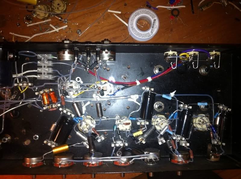
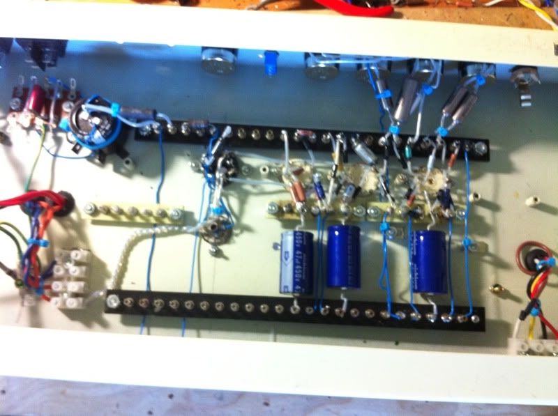
Top is my Harvard, I laid the tubes out in a line Fender/Marshall style intending to use a board but I got lazy and just used lug strips. I don't really consider it ptp, kind of a lazy hybrid.
2nd is my Lightning clone, I would call it 100% ptp.
3rd is a Matchless DC30, I would call it 100% ptp.
Last is a Mararntz 8B, classic high-class ptp work.
You do not have the required permissions to view the files attached to this post.
Re: Point-to-point wiring order
I think you've got to allow a tag strip here and there. There are just too many thingies in a guitar amp to avoid it unless the sun, moon, planets all line up for you. Here's PTP. On the copper colored one, I finally broke down and cut a 4 lug length of yellow board for the tremolo, as I just couldn't figure how to hang all that on one 12AX7 socket. That board also sits above where the choke wires enter the chassis. Since the amp works without the tremolo, I figured I'd allow it. 
What's not allowed is when you line up the tag strips and use them like a turret board. That's not PTP, IMO. Nothing wrong with doing that. I've done it myself. Works great -- poor man's turret board. Just not really PTP.
What's not allowed is when you line up the tag strips and use them like a turret board. That's not PTP, IMO. Nothing wrong with doing that. I've done it myself. Works great -- poor man's turret board. Just not really PTP.
You do not have the required permissions to view the files attached to this post.
-
diagrammatiks
- Posts: 558
- Joined: Sun Mar 27, 2011 12:28 am
Re: Point-to-point wiring order
ya you need tags. There's just specific qualifiers for using turrets and tags.
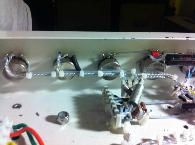
Theoretically if a component had sufficient leads and a way to mount it on the chassis you wouldn't need to use tags.
A lot of the old mil-spec components had clamps for resistors,capacitors, diodes etc.
This is my tinker box.
[IMG:800:597]http://i625.photobucket.com/albums/tt33 ... dc1327.jpg[/img]
a 2 channel with a class5 pre
[IMG:800:597]http://i625.photobucket.com/albums/tt33 ... cb59c0.jpg[/img]
twisting multiple pairs of solid core wire because i clearly have too much time on my hands.
[IMG:800:597]http://i625.photobucket.com/albums/tt33 ... e404-1.jpg[/img]