Bazzman

General discussion area for tube amps.

Moderators: pompeiisneaks, Colossal

User avatar
Lynxtrap
Posts: 354
Joined: Fri Feb 18, 2011 12:37 pm
Location: EU

Bazzman

Post by Lynxtrap »

I'm new here, so: Hi everybody :)

I'm planning a makeover for my old Fender Bassman Ten. As you may notice, one channel is a "Z" preamp, the other is a sort of AB763 'Normal' channel. I'm going with the stock transformers, using a pair of KT66 in the output.
This is still on the drawingboard. I'd very much appreciate any comments, criticism, suggestions etc. The bit I'm most unsure about is the B+/filter section.
At the moment it's a mix of values borrowed from the good doctor and Leo.

Thanx

[img:1000:713]http://i1181.photobucket.com/albums/x43 ... 2-webb.jpg[/img]
Last edited by Lynxtrap on Sun Jan 22, 2012 11:08 pm, edited 1 time in total.
User avatar
rdjones
Posts: 818
Joined: Tue Aug 31, 2010 2:20 am
Location: Music City, TN

Re: Bazzman

Post by rdjones »

As drawn, the B+ D point would be higher than C, and point E has no filter.
Bright caps are a bit much.
No NFB ?

rd
User avatar
Lynxtrap
Posts: 354
Joined: Fri Feb 18, 2011 12:37 pm
Location: EU

Re: Bazzman

Post by Lynxtrap »

rdjones wrote:As drawn, the B+ D point would be higher than C, and point E has no filter.
Bright caps are a bit much.
No NFB ?

rd
The C (PI) are values from a schematic of a Route66, and do seem a bit high (or low in voltage) to me. Then I sort of estimated (or should I say guessed) more of a fendery value for the 12AX7 preamp. Is it a problem that D is higher than C?
What do you mean with E having no filter...? I thought the corresponding 20uF cap would be that node's filter.

The bright cap is actually stock in the BM10, but I'll take a look at that.

I'm not sure about the NFB. I have thought of a standard blackface prescence circuit, then I decided to have each channel drive it's own half of the PI. I've also thought about having a post-PI master vol, or a Vox-style cut control. And somewhere in that process the NFB went out
:)
Do you think it will need feedback?
User avatar
jjman
Posts: 753
Joined: Sat Oct 06, 2007 2:33 pm
Location: Central NJ USA

Re: Bazzman

Post by jjman »

When driving the PI from both/either grid, I've always seen the PI plate resistors as the same value. In your case the EF86 side would be balanced but the 12ax7 side would be significantly relatively unbalanced. Making both the same value would make both slightly unbalanced, in a balanced way. 8)
If it says "Vintage" on it, -it isn't.
User avatar
rdjones
Posts: 818
Joined: Tue Aug 31, 2010 2:20 am
Location: Music City, TN

Re: Bazzman

Post by rdjones »

Is this the later ultralinear BM10 ?
The tonestack on the so-called normal channel is not typical Fender on either version.
Lynxtrap wrote:The C (PI) are values from a schematic of a Route66, and do seem a bit high (or low in voltage) to me. Then I sort of estimated (or should I say guessed) more of a fendery value for the 12AX7 preamp. Is it a problem that D is higher than C?
No, just something to be aware of since Fender convention is progressively lower voltages in order of the letters.
What do you mean with E having no filter...? I thought the corresponding 20uF cap would be that node's filter.
The dropping resistor becomes part of the load when the cap is before rather than after. (C and E both)
The bright cap is actually stock in the BM10, but I'll take a look at that.
Right, but 300pF is higher than the usual 120pF Fender value.
.0068 (6800 pF !) on the EF86 channel is way high.
I'm not sure about the NFB. I have thought of a standard blackface prescence circuit, then I decided to have each channel drive it's own half of the PI. I've also thought about having a post-PI master vol, or a Vox-style cut control. And somewhere in that process the NFB went out
:)
Do you think it will need feedback?
I don't know if it will need feedback but it will certainly change the character and lose the Fender-ness.

rd
User avatar
billyz
Posts: 1305
Joined: Fri Aug 10, 2007 6:17 pm
Location: Spokane, WA
Contact:

Re: Bazzman

Post by billyz »

You don't use both artificial center tap filaments and transformer center tapped. Just use one or the other. The 100 ohm resistors will provide some margin of safety (burn open) if a filament short occurs.
User avatar
Lynxtrap
Posts: 354
Joined: Fri Feb 18, 2011 12:37 pm
Location: EU

Re: Bazzman

Post by Lynxtrap »

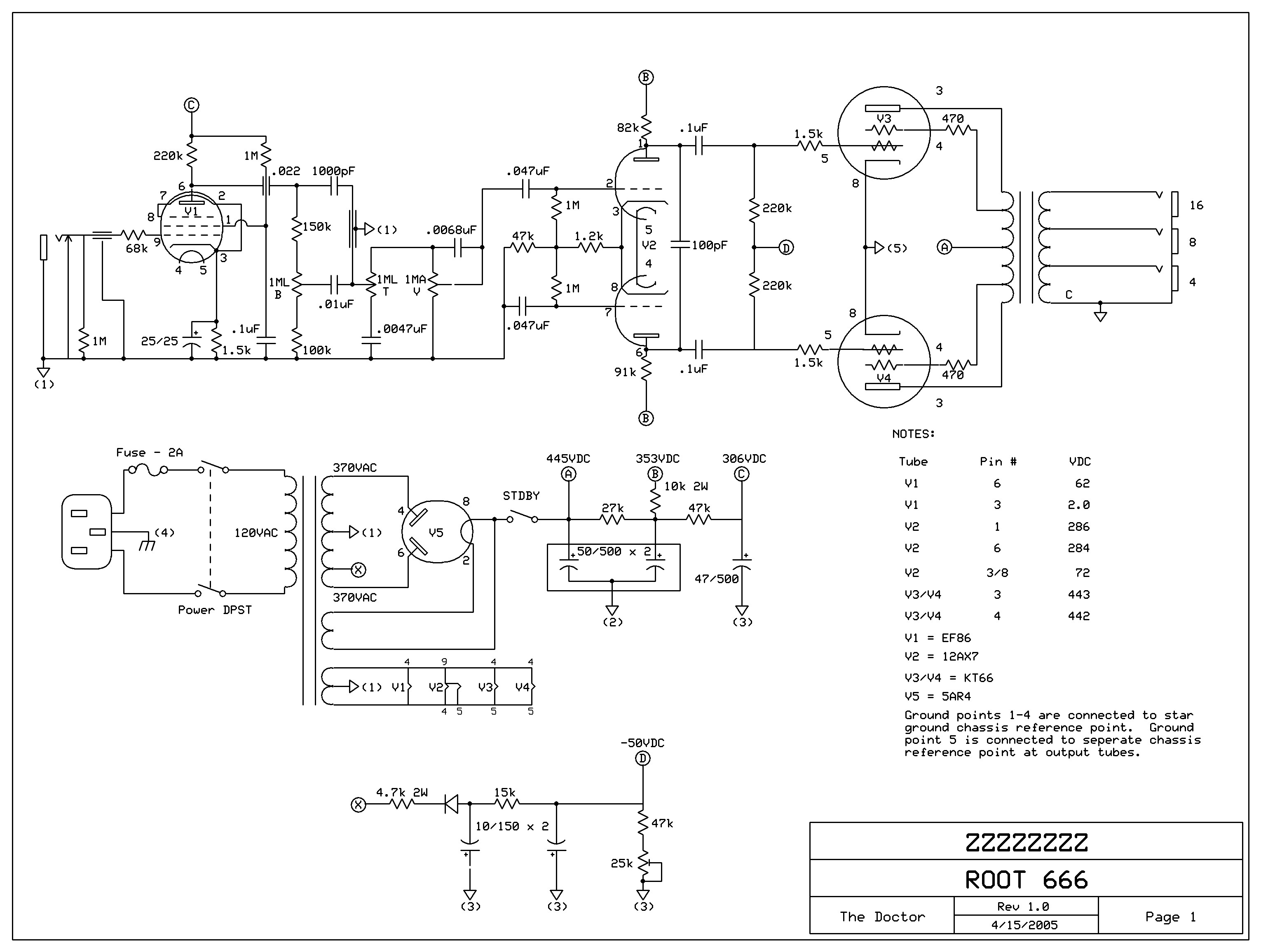
billyz wrote:You don't use both artificial center tap filaments and transformer center tapped. Just use one or the other. The 100 ohm resistors will provide some margin of safety (burn open) if a filament short occurs.
rdjones wrote:The dropping resistor becomes part of the load when the cap is before rather than after. (C and E both)
Well, you see, this is where I'm kind of lost :oops: I'm simply in over my head with the power supply, don't have the knowledge. In other words, I don't really understand those answers. (This is where you might say "then maybe you shouldn't be doing this") :wink:

About the filtering, I thought that all resistors in a series chain were part of the load. But I guess I didn't really know how the caps come in to play.

Billyz, are you talking about the rectifier filaments? Artificial center tap...? :oops: I have some reading to do.

About the PI plate resistors, I simply forgot to look over those and redraw after deciding on the double input. Thanks for the tip.

And no, this is not the UL BM10. If so, I would have gone with the UL of the R66 as in the original Z.

The "Fender channel" tonestack is already modded as in the schematic, so it's not stock BM10.

Here are some links:

http://www.6v6power.ru/inf/Amplifier/Fe ... %20Amp.jpg

http://www.prowessamplifiers.com/schema ... oute66.jpg
User avatar
billyz
Posts: 1305
Joined: Fri Aug 10, 2007 6:17 pm
Location: Spokane, WA
Contact:

Re: Bazzman

Post by billyz »

Not your rectifier it has a directly heated cathode. or to put it another way, the the cathode is the filament and vice versa. I am talking about the heater filaments for the audio tubes, ie 6l6 and 12ax7's.
surfsup
Posts: 1513
Joined: Mon Nov 29, 2010 12:21 am
Location: Chicagoland

Re: Bazzman

Post by surfsup »

At the very bottom of your schemo, you have two grounds for your tube heaters: the centertapped groung in the center AND the two 100Rs to ground.

If you use the two 100Rs, tape off the centertap ground and dont use it.
User avatar
Lynxtrap
Posts: 354
Joined: Fri Feb 18, 2011 12:37 pm
Location: EU

Re: Bazzman

Post by Lynxtrap »

Thanks. Staring at different schematics tonight I realized that those resistors to ground had to be the "virtual ground". The amp already has that so I guess I'll keep it that way.
I'm starting to think I'll have to look over that B+ line again. Since I don't know how to calculate the voltages it's mostly a matter of borrowing from other designs.

Let's say I'd just use the stock BM10 values and layout in the filter section, but want to supply an EF86 in the first channel. Is there a simple way, like 'add one xxxK resistor and rock'?

Looking at the R66 schematic linked above, it's noted to have about 70V at the PI plates and 62V at the EF86 plate. Seems low to me.
timford
Posts: 28
Joined: Tue Sep 27, 2011 3:32 am

Re: Bazzman

Post by timford »

Lynxtrap wrote:
Looking at the R66 schematic linked above, it's noted to have about 70V at the PI plates and 62V at the EF86 plate. Seems low to me.
Not sure if this is much help, but on my KT45 which is an almost identical schematic but different transformers and output voltages, tubes etc, the ef86 plate runs around 95v, and the plate of the PI runs around 300v (pins 1 and 6), and the cathodes are at 78v (pins 3 and 8 ).

Probably running the preamp tubes completely differently though, as the voltages that correspond to A B and C on your schematic are 468, 462 and 426 respectively. Having not poked around inside a 66, I've got no idea what the preamp tubes run at, and whether the schematic voltages listed are correct.

I might have a go at drawing the 2 ef86 load lines as a learning aid for myself.
User avatar
Lynxtrap
Posts: 354
Joined: Fri Feb 18, 2011 12:37 pm
Location: EU

Re: Bazzman

Post by Lynxtrap »

timford wrote: Having not poked around inside a 66, I've got no idea what the preamp tubes run at, and whether the schematic voltages listed are correct.

I might have a go at drawing the 2 ef86 load lines as a learning aid for myself.
Well, if you come up with something, it would great to have a look.
Are the voltages correct - I don't know. I don't know the source of the schematic. It just seems to be the only one floating around. Some of them seem a bit odd to me.
User avatar
Luthierwnc
Posts: 998
Joined: Sat Feb 18, 2006 10:59 am
Location: Asheville, NC

Re: Bazzman

Post by Luthierwnc »

Get your hands on the hand-drawn Matchless DC30 schematic on the web. It does very close to what you are trying in terms of matching output on the channels. Especially look at the post-PI cut control. That may be your last chance to tame a squealer.

For extra credit, consider using the FX jacks on that schematic -- way more trouble since you are using both sides of the PI but worth it. I've had success using a Dumbleator-style loop with pentode front-ends (or the Clubman pentode second stage). It adds a warmth you can't get by distorting transistors before you hit the first tube. If you don't end up using it, you are out a couple jacks and some coax (very important; the coax).

Another mod would be to hang switchable boost resistors to the bottom of the tone-stacks (another Dumble-esque idea). I haven't done this for the pentode (hence the trimmer) but the Fender mod is old as dirt and a 180k resistor works great. Since you only need a simple on-off, you can put both sides on a DPDT mini or P/P pot.

Finally, I've never liked the idea of having to pull the cord to change channels or running an extra patch cord between the jacks on a ground-up build. Sketch more possibilities to make that switchable rather than two jacks. I've never done it but one day I'll do an autopsy on a DPDT switch to see if I can make one side on-on-on and the other on-none-on so you can use either or both channels and still ground the unused one.

Skip
You do not have the required permissions to view the files attached to this post.
User avatar
Lynxtrap
Posts: 354
Joined: Fri Feb 18, 2011 12:37 pm
Location: EU

Re: Bazzman

Post by Lynxtrap »

Those are good ideas, Luthier.
I thought about channel switching. It would also be great to be able to drive both channels bridged at the inputs. But I guess they'll be out of phase with each other with the EF86 in ch 1.

Thing is, I already have an OTS 50W. So I want to stay away from D-territory with this one.
But I do have one available switch in ch 1. And we can't have that, can we :lol:
User avatar
Luthierwnc
Posts: 998
Joined: Sat Feb 18, 2006 10:59 am
Location: Asheville, NC

Re: Bazzman

Post by Luthierwnc »

You should be able to bridge them. The phase is the same at the jacks. If you don't want to, here's the switch for one or the other. I put grid leak resistors on both sides because a shared resistor on the jack side of the switch can pop. You could also just put the grid leak resistor between two throws on one side of the switch so when one side is grounded, the other has one meg referenced to ground. sh
You do not have the required permissions to view the files attached to this post.
Post Reply