What's the best critria to use for matching up pairs of tubes for a push-pull amp? I don't have a tube tester, so I install all my tubes one by one into a Champ clone and measure idling current, then group them up based on that.
Some of the tubes have Gm marked on the boxes, and the ones that seem matched in terms of Gm don't necessarily match up in terms of idling current.
I suppose either method gets you in the ballpark, but my guess is that Gm would be the best way to match them?
Matching by Gm or Ip?
Moderators: pompeiisneaks, Colossal
-
Andy Le Blanc
- Posts: 2582
- Joined: Sat Dec 22, 2007 1:16 am
- Location: central Maine
Re: Matching by Gm or Ip?
look in the back of any RCA receiving tube manual in the "Electron Tube Testing"
section and look at the "dynamic transconductance test".
the hard part is setting up a rig where you control plate and screen voltages
with accuracy and stability, to get good measurements, under known test conditions.
section and look at the "dynamic transconductance test".
the hard part is setting up a rig where you control plate and screen voltages
with accuracy and stability, to get good measurements, under known test conditions.
lazymaryamps
-
David Root

- Posts: 3540
- Joined: Fri Aug 04, 2006 3:00 pm
- Location: Chilliwack BC
Re: Matching by Gm or Ip?
In practice we in the MI amp crowd use cathode current at idle (Ik) as this determines the tubes' bias. Hi fi guys like to match both Ik and Gm. This is difficult!
In most MI amp circuits up to 5mA discrepancy between Ik in a pair, in my experience, just ensures some nice jangle in the tone.
In a Dumble type build, where the power amp is much more towards a hi fi amp, I want 1mA max. and fiddle with the PI AC balance for harmonic optimization.
Using just Gm won't tell you anything useful because Gm and Ik simply don't correlate that well in the average production tube, and that goes for NOS as well as current production. Maybe in '50s Marconi/GEC KT66/88s and GEC 7729s and similar lofty audiophile grade stuff, but you need a second mortgage to buy those these days.
-
Cliff Schecht
- Posts: 2629
- Joined: Wed Dec 30, 2009 7:32 am
- Location: Austin
- Contact:
Re: Matching by Gm or Ip?
I was definitely second guessing myself when I was considering dropping $200 on a pair of real GEC KT88's that were only slightly used and well matched. While that's not a bad deal in today's market, I don't need those tubes and that same $200 went towards at least 30-40 other tubes whose value in comparison was much higher.
Gm just tells you that if you tickle the grid with X amount of voltage you will get a wiggle of Y amount of current at the plate. This is a "unitless" value or, in other words, gm represents a ratio of plate current to grid voltage (think of it as a gain). As others said, plate current is nearly independent of gm. Matching gm just means that two tubes will change plate currents at the same ratio for a certain amount of grid voltage change, but it doesn't tell you anything about what amount of current each tube is going to self-bias to.
I also agree 100% with what David says about matching. For most every amp that relies on the power stage for distortion, I prefer some mismatch. Perfectly matched tubes cancel even harmonics by nature which can kill the liveliness of an amp and make it too harsh. I never match tubes myself, I do test them to make sure they aren't 20mA apart but I like them to be only relatively close, not perfectly matched. Tubes drift over time anyways and so even if they match now, they might not match two weeks from now after use (this is where burn-in helps). This is why we all hoard tubes, it's good to have a lot of sets around to test different brands/styles of the same power tube in your amp to see if one brings things to life. There's no magic here mind you, some tubes just have a better harmonic profile in some amps than others.. Some amps love only NOS tubes and hate new stock whereas others sound fantastic with a fresh set of JJ's but not any better with NOS. Gotta roll those tubes until you find what you're after tone-wise!
In amps like a Dumble which rely purely on preamp distortion it makes sense to match the power tubes. In a Fender Twin, anything with a SS preamp or anything meant for mostly clean tones (Hiwatt comes to mind) I would use matched power tubes.
Cliff Schecht - Circuit P.I.
-
VacuumVoodoo

- Posts: 924
- Joined: Fri Feb 17, 2006 6:27 pm
- Location: Goteborg, Sweden
- Contact:
Re: Matching by Gm or Ip?
Transconductance is the name and it's not unit less. The unit is inverse of Ohm, called Siemens. Both were German physicists. Gain, or amplification factor is unit less because it relates magnitudes of the same property.
Ye. I know, I'm a stickler for details and can't turn off old lecturers habits.
Ye. I know, I'm a stickler for details and can't turn off old lecturers habits.
Aleksander Niemand
------------------------
Life's a party but you get invited only once...
affiliation:TUBEWONDER AMPS
Zagray!-review
------------------------
Life's a party but you get invited only once...
affiliation:TUBEWONDER AMPS
Zagray!-review
-
Lonely Raven

- Posts: 878
- Joined: Fri Nov 16, 2007 4:09 am
- Location: Bolingbrook, IL
- Contact:
Re: Matching by Gm or Ip?
So in laymen terms, can we match tubes in a champ like the OP was talking about? Or if I have a pile of 6L6 and want to match them up, and I just keep plugging and measuring in my Super Reverb till I find a pair within 5mA?
Jack of all Trades,
Master of None
Master of None
-
Cliff Schecht
- Posts: 2629
- Joined: Wed Dec 30, 2009 7:32 am
- Location: Austin
- Contact:
Re: Matching by Gm or Ip?
Mhos (or more commonly micromhos) is the unit and yes it is in Siemens. You are right in that it's not unitless because it works out to amps/volt which equates to 1/resistance. Gain is volts/volt which does work out to be unitless. Silly me!VacuumVoodoo wrote:Transconductance is the name and it's not unit less. The unit is inverse of Ohm, called Siemens. Both were German physicists. Gain, or amplification factor is unit less because it relates magnitudes of the same property.
Ye. I know, I'm a stickler for details and can't turn off old lecturers habits.
Raven: Yes this is not only an acceptable method but IMO preferable to just shoving tubes in a tube tester. It's always best to test tubes under real working conditions to get a feel for how they will act in a real world circuit. My best 12AX7 tester is a little two-tube wonder with a 6BM8 power stage. I make one of the 12AX7 stages switchable so I can test the tube in question both under clean and dirty operating conditions.
Cliff Schecht - Circuit P.I.

Re: Matching by Gm or Ip?
Maybe Mr. V.Voodoo will comment further on my understanding of transconductance. If what I think is correct, it is important. How important? I'm not sure.
Wiki says: "For vacuum tubes, transconductance is defined as the change in the plate(anode)/cathode current divided by the corresponding change in the grid/cathode voltage, with a constant plate(anode)/cathode voltage. Typical values of gm for a small-signal vacuum tube are 1 to 10 millisiemens." (I take the / character to mean you use one or the the other and not a fractional expression, as the text says "divided" for the math operation. Besides, Ip and Ik should have a linear relationship.)
To find Gm, without calculus, vary the bias voltage and take several readings. Or vary the plate voltage (which will force a change in output current). This will give you the needed points of data to make the calculation.
So, over a given relevant range, you can find and "match" tubes that will behave similarly while in use. If you find the tubes are matched at expected idle, some guess at mid point, and your best estimate of full tilt, then a transconductance match provides some useful information. Whether that will sound good, great, or bad is a whole other subject.
When you do it this way, you are also matching for plate current, as well as the expected change in plate current over a range of voltages. It should provide a darn good match, if that's important to you.
If you hold plate voltage steady, to find Gm set bias voltage at two different points: Ip(a) - Ip(b) / Vg(a) - Vg(b) This will qualtify Gm. Get two other data points and calc again. It starts to set up a curve.
Ip(a) is plate current when bias voltage is set at "a".
Ip(b) is plate current when bias voltage is set at "b".
Vg(a) is bias voltage set at (a)
Vg(b) is bias voltage set at (b)
Example, three sets or data points, holding plate voltage constant and varying bias voltage:
40mA at -11V
34mA at -13V
30mA at -15V
(40-30)/(-11-15) * 1000 = 2500
(40-34)/(-11-13) * 1000 = 3000
(34-30)/(-13-15) * 1000 = 2000
You now have three Gm calculations. Look for two tubes that show the same or nearly the same results. More data points will start to suggest a curve. No calculus needed, but primitive. With Excel at everyone's disposal (or Open Office if you need something free), anyone can manage this.
You can do a similar thing if you can hold bias voltage constant and vary plate voltage. As I said above, plate current will change with plate voltage.
What I showed above can be done in most fixed bias amps that have variable bias voltage. You can find data sets at very hot bias, something cooler near that you think is near the middle, and something cold but not freezing cold. To be fair, I should note, that, as you vary bias voltage, plate voltage will change a bit. It's my impression that a narrow range of plate voltages doesn't throw off the results too much. Also, this type of analysis is at three points of idle. As a practical matter, without a test rig, your data are not of the highest quality. As others pointed out, we're talking about guitar amps here, not hi-fi.
Most amps don't have variable plate voltage that can be easily controlled while under test. For that, you probably need to build a test rig or buy one.
Wiki has what looks to me to be a pretty good write up. http://en.wikipedia.org/wiki/Transconductance
I hope I did OK here. I'm strictly an amateur without an engineering background. No one showed this to me. I did it based on what I read in Wiki. Comments and criticism invited. I recognize that I may have missed the boat but I'm willing to put it out there. Thanks.
Re: Matching by Gm or Ip?
Thanks guys, lots of good info. I agree with the 'close enough for hand grenades and guitar amps' theory. I don't believe a pair of tubes has to be precisely matched, but it's good if they are somewhat close.
Let me rephrase my question though: When you buy a "matched pair" of tubes, how are they matched? By idling current, or Gm? Or is there not really any generally accepted protocol?
Thanks again for all your input!
Let me rephrase my question though: When you buy a "matched pair" of tubes, how are they matched? By idling current, or Gm? Or is there not really any generally accepted protocol?
Thanks again for all your input!
Re: Matching by Gm or Ip?
IMO, this is exactly the question you need to ask the seller. Ask that and ask for a description of the procedure. Gm considers Ip. So, get the details. Either one could prove to be useful depending on what the test actually was. If the test was run at Vp = 150V, that's not "real world" and probably doesn't mean much. That's why you ask for details.boots wrote:When you buy a "matched pair" of tubes, how are they matched? By idling current, or Gm? Or is there not really any generally accepted protocol?
If you don't like the answer, look elsewhere. If they were "matched" in a primitive tube tester, "D'oh, they were both 92 on my el cheapo tube tester." they aren't matched. If the seller has and uses a legit testing rig, chances are that a) he knows what he's doing and b) that you'll get what you paid for.
-
Prairie Dawg
- Posts: 156
- Joined: Sun Jan 10, 2010 2:19 am
- Location: Windsor Heights, Iowa
Re: Matching by Gm or Ip?
This discussion is part of the reason why I built a tube matcher. I am a lot more confident about the parts I sell to people when I can test them myself beforehand. Also mighty handy when trying to troubleshoot the fault detection circuit in an SVT. I can test them at over 600v.Phil_S wrote:IMO, this is exactly the question you need to ask the seller. Ask that and ask for a description of the procedure. Gm considers Ip. So, get the details. Either one could prove to be useful depending on what the test actually was. If the test was run at Vp = 150V, that's not "real world" and probably doesn't mean much. That's why you ask for details.boots wrote:When you buy a "matched pair" of tubes, how are they matched? By idling current, or Gm? Or is there not really any generally accepted protocol?
If you don't like the answer, look elsewhere. If they were "matched" in a primitive tube tester, "D'oh, they were both 92 on my el cheapo tube tester." they aren't matched. If the seller has and uses a legit testing rig, chances are that a) he knows what he's doing and b) that you'll get what you paid for.
If you believe in coincidence you're not looking close enough-Joe leaphorn
Re: Matching by Gm or Ip?
Care to tell us a little about your rig and how you go about testing/matching? Curious minds want to know.
-
Prairie Dawg
- Posts: 156
- Joined: Sun Jan 10, 2010 2:19 am
- Location: Windsor Heights, Iowa
Re: Matching by Gm or Ip?
I have a Hickock 532 for general gM testing chores. I found a schematic for a tube matcher at the old Priceless Amps websitePhil_S wrote:Care to tell us a little about your rig and how you go about testing/matching? Curious minds want to know.
http://priceamp.home.comcast.net/~priceamp/
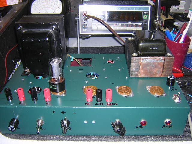
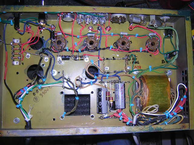
Mine is a bit different because I used a NOS television power transformer without a bias winding so I had to wire it up ala JTM45 off one side of the HT. The filament transformer came from an organ and the chassis came from an old Bogen PA amp. Believe it or not the filament transformer is the one on the left, it was running about 40 12AU7s and even with 4 EL34s my filament voltage doesn't go below 6.4v. The power transformer is a lot heftier than the one that Jack used, it dishes out about 300 ma.
Line voltage is run through a variac before it hits the power transformer, it is rectified and filtered and supplied to the plates. Here I had to install plate load resistors (82 ohm 1w, which are not on the Price schematic) because with 6550s or KT88s anything above 400v would oscillate. I could hear it through an am radio and the voltages would go nuts. Now it's nice and stable and when I get an amp in for service the first thing I do is test the tubes on my Hickok and on the matcher. Not set up for EL84s yet but that's coming.
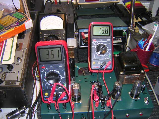
So what I do is start low and slow, monitoring bias voltage as B+ comes up. Once I reach the plate voltage I want to test at, I set the bias voltage and then start looking at cathode current. It's the standard read across a 1 ohm resistor. The way I cal check it is to test the same tube at the same settings in each socket. If it's within .2 ma I call it good.
It was easy enough to build once i had the parts.
When I'm matching power tubes I like to run them at maximum plate voltage in the GE essential characteristics manual and set the bias voltage at 48, 40 or 36v and then, if they're within 2 ma highest to lowest and the gM is pretty much the same, I call them close.
Here's a couple pics.
[IMG:640:480]http://img.photobucket.com/albums/v435/ ... CN4255.jpg[/img]
[IMG:640:480]http://img.photobucket.com/albums/v435/ ... CN4256.jpg[/img]
[IMG:640:480]http://img.photobucket.com/albums/v435/ ... CN4251.jpg[/img]
If you believe in coincidence you're not looking close enough-Joe leaphorn