New Build - Express
Moderators: pompeiisneaks, Colossal
Re: New Build - Express
Yes, but that is with the bulb current limiter on, so it may show as less than the 6.3 volts.
-
amplifiednation
- Posts: 2091
- Joined: Sun Dec 26, 2010 6:19 pm
- Location: Boston
- Contact:
Re: New Build - Express
You really need to get that bias figured out or you will continue to red plate tubes. I think you probably know this. I was redplating a tube on my power up too and I want to say that was at -28. Once I got to -30 things have been fine.
I would double check your bias resistor and make sure it is correct. What value pot did you use?
I would double check your bias resistor and make sure it is correct. What value pot did you use?
Amplified Nation
www.amplifiednation.com
@ampnation
www.amplifiednation.com
@ampnation

Re: New Build - Express
Think about it, you have no tubes drawing current from the filament winding. If you don't have 6.3V, you have a problem. A bulb limiter is not going to cause you to lose 25% of your heater filament voltage.Picker wrote:Yes, but that is with the bulb current limiter on, so it may show as less than the 6.3 volts.
The bias is a another issue, it should drop slightly when you have a load. Nevertheless, you should have more there. Check AC before the diode and DC at the bias cap.
TM
Re: New Build - Express
Do you have any gut pics of this amp in its current config?
Todd
Todd
Re: New Build - Express
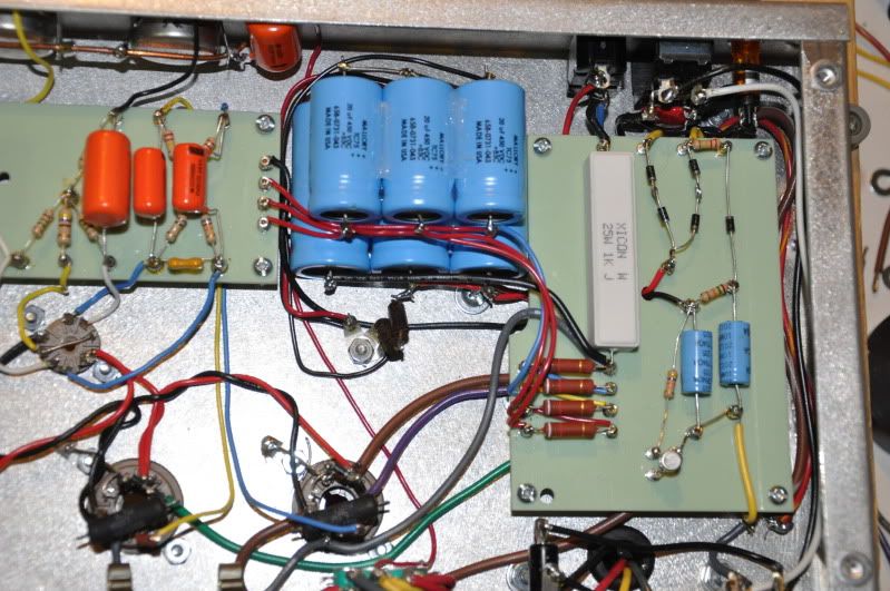
Here's one of the PS Board section. Let me know if you need others.
[IMG:799:531]http://i54.photobucket.com/albums/g94/r ... C_0904.jpg[/img]
[IMG:799:531]http://i54.photobucket.com/albums/g94/r ... C_0904.jpg[/img]
-
amplifiednation
- Posts: 2091
- Joined: Sun Dec 26, 2010 6:19 pm
- Location: Boston
- Contact:
Re: New Build - Express
Everything looks correct, including the resistor values. Can you take the readings that Tonemerc suggested?
Do you know what pot value you used for the trimmer? Is there anything connected to the lug left of the wiper? There should be a jumper from the 10uf cap c21 to both outside lugs
Do you know what pot value you used for the trimmer? Is there anything connected to the lug left of the wiper? There should be a jumper from the 10uf cap c21 to both outside lugs
Amplified Nation
www.amplifiednation.com
@ampnation
www.amplifiednation.com
@ampnation
Re: New Build - Express
Taylor, I'm with ya. I blew the pic up and I'm not sure what's going on with that bias trimmer. It will work wired like that , but if for some reason the resistive element opens, your bias circuit goes open.amplifiednation wrote:
Do you know what pot value you used for the trimmer? Is there anything connected to the lug left of the wiper? There should be a jumper from the 10uf cap c21 to both outside lugs
Re: New Build - Express
The pot is the 25k 1/2 watt recommended by the BOM and purchased from Mouser. I'll check the wiring of it (not sure I have it right) and also will check the things ToneMerc mentioned.
I think I do have it incorrect. Right now, instead of a separate lead going to the cap, I have a jumper from the bottom lead to the wiper and then to the cap. I'll try disconnecting that jumper and running a separate lead to the other cap.
I think I do have it incorrect. Right now, instead of a separate lead going to the cap, I have a jumper from the bottom lead to the wiper and then to the cap. I'll try disconnecting that jumper and running a separate lead to the other cap.
-
amplifiednation
- Posts: 2091
- Joined: Sun Dec 26, 2010 6:19 pm
- Location: Boston
- Contact:
Re: New Build - Express
You did a great job wiring up the amp. It looks well done. I'm trying to get mine to be less noisy, I rewired some stuff and now its more problematic than it was before! You are in for some fun my friend.
I don't know if rewiring that trimmer will be any differently electrically but you definately should do it.
I don't know if rewiring that trimmer will be any differently electrically but you definately should do it.
Amplified Nation
www.amplifiednation.com
@ampnation
www.amplifiednation.com
@ampnation
Re: New Build - Express
As long as the two lugs are connected together you are fine. However, if you want to be layout correct, then each terminal should have a dedicated jumper back to the first bias cap.Picker wrote:I think I do have it incorrect. Right now, instead of a separate lead going to the cap, I have a jumper from the bottom lead to the wiper and then to the cap. I'll try disconnecting that jumper and running a separate lead to the other cap.
Re: New Build - Express
Oops... I was already downstairs moving it. I actually moved it to the 2nd cap. - see picture below.
Taking readings at the top of the Diode stack I get 234 volts on each side. If I read at the bottom of the stack where they meet, I get 738.
Checking DC on the c21 and c22 I wasn't sure what I was to check. From the negative side of the cap I get -27 and -32. Checking on the positive side I get nothing.
I also check the heaters again and get 4.9
[IMG:799:531]http://i54.photobucket.com/albums/g94/r ... C_0909.jpg[/img]
Re: New Build - Express
If you have -32V at the negative junction of C22, then I think you are fine because when it's loaded with current draw, it's going to drop. Now if you only have 234VAC at your HT tap, it would explain why the bias voltage is slightly low.Picker wrote:Oops... I was already downstairs moving it. I actually moved it to the 2nd cap. - see picture below.
Taking readings at the top of the Diode stack I get 234 volts on each side. If I read at the bottom of the stack where they meet, I get 738.
Checking DC on the c21 and c22 I wasn't sure what I was to check. From the negative side of the cap I get -27 and -32. Checking on the positive side I get nothing.
I also check the heaters again and get 4.9
[IMG:799:531]http://i54.photobucket.com/albums/g94/r ... C_0909.jpg[/img]
234VAC: seems low
738VDC: I'm scratching my head here, it's impossible. Even if you managed to wire 234VAC as a doubler, it's only about 660VDC unloaded.
5V: Hmmm, it's possible that the brown leads are mistakely wired for 5V and not 6.3V. Which PT are you using? Does it have 5V taps, if so check to see if those are actually 6.3V
Confirm: no tubes and no bulb limiter were installed, correct?
Re: New Build - Express
No tubes, but with the bulb limiter.
I'm using the Hayboer transformers from RJ. I'll check and see if maybe there is i 5 volt, but I think I selected the correct wires.
I'll also check the combined diode one again. I may have written that down wrong.
I'm using the Hayboer transformers from RJ. I'll check and see if maybe there is i 5 volt, but I think I selected the correct wires.
I'll also check the combined diode one again. I may have written that down wrong.
Re: New Build - Express
Not sure what to say... I checked again Volts AC and got about 234 at the top and 728 at the bottom of the stack (still reading volts AC not DC)
To be sure I also checked at the other end of the red wire next to the cap stack and got the same 728
The Transformer is
Heyboer HTS-5199-M50 Power Tansformer
Heyboer HTS-9384 Output transformer
To be sure I also checked at the other end of the red wire next to the cap stack and got the same 728
The Transformer is
Heyboer HTS-5199-M50 Power Tansformer
Heyboer HTS-9384 Output transformer
-
amplifiednation
- Posts: 2091
- Joined: Sun Dec 26, 2010 6:19 pm
- Location: Boston
- Contact:
Re: New Build - Express
What do you mean at the bottom of the cap stack? There shouldnt be AC on the caps.Picker wrote:Not sure what to say... I checked again Volts AC and got about 234 at the top and 728 at the bottom of the stack (still reading volts AC not DC)
To be sure I also checked at the other end of the red wire next to the cap stack and got the same 728
The Transformer is
Heyboer HTS-5199-M50 Power Tansformer
Heyboer HTS-9384 Output transformer
What do you get for AC across the two yellow secondary wires before the diodes?
Amplified Nation
www.amplifiednation.com
@ampnation
www.amplifiednation.com
@ampnation