
Keep at it Taylor your doing a fine job.
Mark
Rocket w/ Reverb
Moderators: pompeiisneaks, Colossal
-
amplifiednation
- Posts: 2091
- Joined: Sun Dec 26, 2010 6:19 pm
- Location: Boston
- Contact:
Re: Rocket w/ Reverb
Checking in...
Got my board all mounted and what not.
Trying to get the reverb driver wired in so I can start wiring up the board.
Did I do this correctly?
Red to B2
Black will be ground (jacks are isolated, I will eventually ground them to the pots)
green is to one of the jacks, then the other jack is going to the grid of V2, blue coming from the driver is to the plate of V3??
I threw a 220k resistor into the grid of V2 in parallel with the wire.
It's tough to see through the board of normsters layout. if you guys could let me know if this is right it would be great.
i saw in angelodp's layout there is a resistor coming from B2?? Do i need to plan on reducing voltage from that point? or am i good coming right off there to the driver?
You do not have the required permissions to view the files attached to this post.
Amplified Nation
www.amplifiednation.com
@ampnation
www.amplifiednation.com
@ampnation

Re: Rocket w/ Reverb
[IMG 1445]http://i260.photobucket.com/albums/ii9/ ... footsw.jpg[/img]
Got my board all mounted and what not.
Trying to get the reverb driver wired in so I can start wiring up the board.
Did I do this correctly?
Red to B2
Ange - Yes, but I created an additional node with a resistor and extra cap
Black will be ground (jacks are isolated, I will eventually ground them to the pots)
Ange - Yes, tie both jack grounds together and run back to pot bus bar.
green is to one of the jacks, then the other jack is going to the grid of V2, blue coming from the driver is to the plate of V3??
Ange - Green to the output jack, other jack to pin 2 of V2, Blue from driver to pin 1&6 ( tied ) V3,
I threw a 220k resistor into the grid of V2 in parallel with the wire.
220k is from ground to pin2 of V2
It's tough to see through the board of normsters layout. if you guys could let me know if this is right it would be great.
i saw in angelodp's layout there is a resistor coming from B2?? Do i need to plan on reducing voltage from that point? or am i good coming right off there to the driver?[/quote]
Ange - That resistor and the additional cap create the extra node in my build. Norm does it differently and I am not sure how to guide you on that.
 1445]http://i260.photobucket.com/albums/ii9/ ... footsw.jpg[/img]
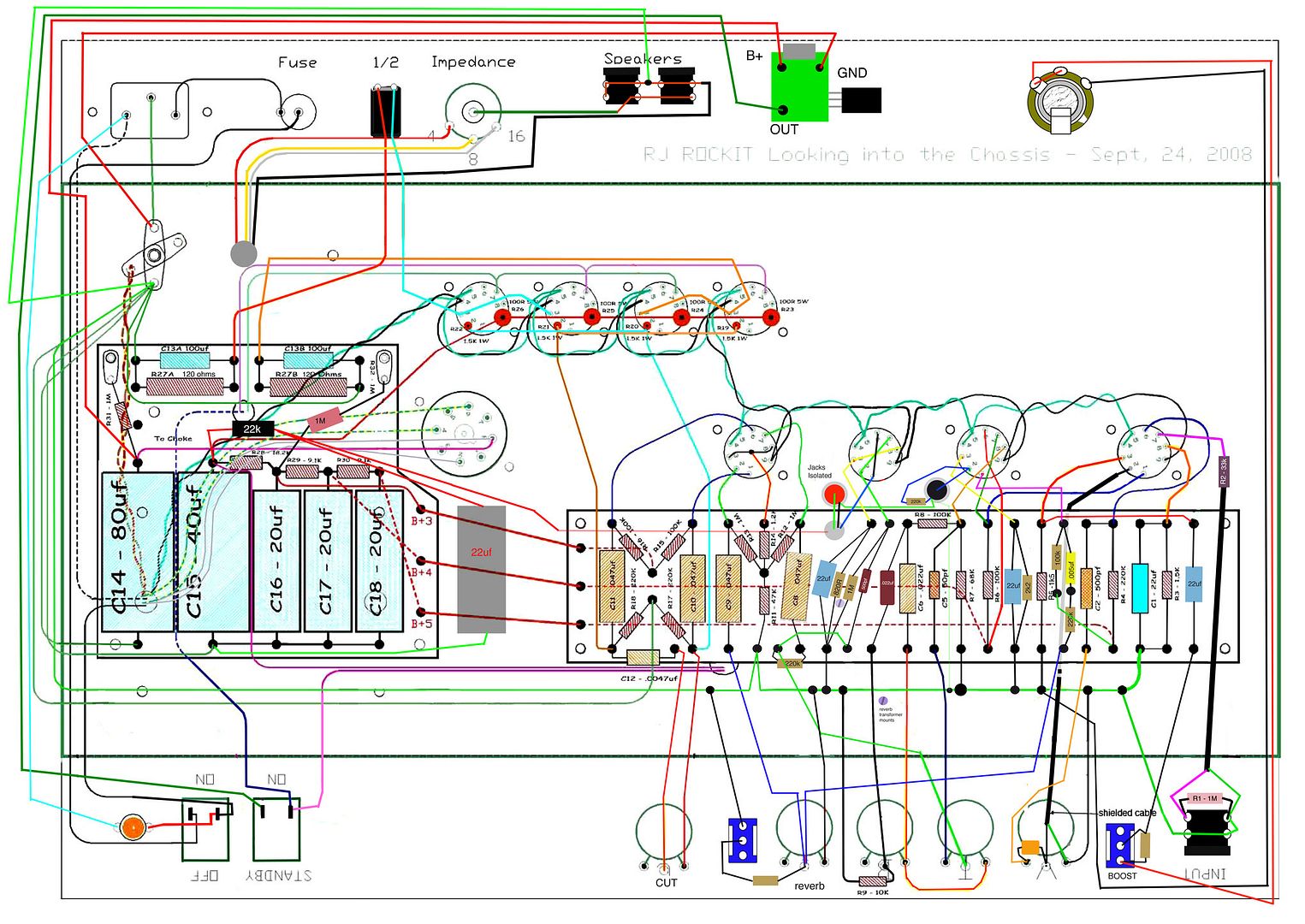
Got my board all mounted and what not.
Trying to get the reverb driver wired in so I can start wiring up the board.
Did I do this correctly?
Red to B2
Ange - Yes, but I created an additional node with a resistor and extra cap
Black will be ground (jacks are isolated, I will eventually ground them to the pots)
Ange - Yes, tie both jack grounds together and run back to pot bus bar.
green is to one of the jacks, then the other jack is going to the grid of V2, blue coming from the driver is to the plate of V3??
Ange - Green to the output jack, other jack to pin 2 of V2, Blue from driver to pin 1&6 ( tied ) V3,
I threw a 220k resistor into the grid of V2 in parallel with the wire.
220k is from ground to pin2 of V2
It's tough to see through the board of normsters layout. if you guys could let me know if this is right it would be great.
i saw in angelodp's layout there is a resistor coming from B2?? Do i need to plan on reducing voltage from that point? or am i good coming right off there to the driver?[/quote]
Ange - That resistor and the additional cap create the extra node in my build. Norm does it differently and I am not sure how to guide you on that.
Re: Rocket w/ Reverb
Driver red to B+2
Black to ground tab Red RCA jack
Green to tip of Red RCA jack
Blue to pin 6 across to pin 1 on V3
V2 pin 7 to tip of other Black RCA jack
220K from V2 pin 7 to Black RCA jack ground lug
Black to ground tab Red RCA jack
Green to tip of Red RCA jack
Blue to pin 6 across to pin 1 on V3
V2 pin 7 to tip of other Black RCA jack
220K from V2 pin 7 to Black RCA jack ground lug
-
amplifiednation
- Posts: 2091
- Joined: Sun Dec 26, 2010 6:19 pm
- Location: Boston
- Contact:
Re: Rocket w/ Reverb
awesome. i def had it wrong.
rewired the 220K resistor. everything else seemed to check out. I drilled the holes in the chassis too big and had to use those big ugly washers. i wish i didn't have to because the end of the jacks are right up against the board. i hope they don't interfere with anything..
rewired the 220K resistor. everything else seemed to check out. I drilled the holes in the chassis too big and had to use those big ugly washers. i wish i didn't have to because the end of the jacks are right up against the board. i hope they don't interfere with anything..
You do not have the required permissions to view the files attached to this post.
Amplified Nation
www.amplifiednation.com
@ampnation
www.amplifiednation.com
@ampnation
moving ahead
be sure that the 220k leads do not hit the chassis. You may have to use a washer in between the board and the standoffs if the RCA's are touching.
Getting there.
Getting there.
-
amplifiednation
- Posts: 2091
- Joined: Sun Dec 26, 2010 6:19 pm
- Location: Boston
- Contact:
Re: Rocket w/ Reverb
they are definately not touchin the chassis. they are touching the bottom of the board, but no turrets or anything. i hope it checks out.
starting wiring in the board nice and slowly. the mounting screw by the cap stack i drilled too close to the turret (or vice versa) so i'm gonna have to change something there, maybe i can get a nylon screw or something that doesn't conduct.
sooo much done, soo much more to do.
starting wiring in the board nice and slowly. the mounting screw by the cap stack i drilled too close to the turret (or vice versa) so i'm gonna have to change something there, maybe i can get a nylon screw or something that doesn't conduct.
sooo much done, soo much more to do.
You do not have the required permissions to view the files attached to this post.
Amplified Nation
www.amplifiednation.com
@ampnation
www.amplifiednation.com
@ampnation
-
amplifiednation
- Posts: 2091
- Joined: Sun Dec 26, 2010 6:19 pm
- Location: Boston
- Contact:
Re: Rocket w/ Reverb
Mark you are the man. Thank you for clearing that upM Fowler wrote:Driver red to B+2
Black to ground tab Red RCA jack
Green to tip of Red RCA jack
Blue to pin 6 across to pin 1 on V3
V2 pin 7 to tip of other Black RCA jack
220K from V2 pin 7 to Black RCA jack ground lug
Amplified Nation
www.amplifiednation.com
@ampnation
www.amplifiednation.com
@ampnation
Re: Rocket w/ Reverb
We can all thank Normster for his great layout and designing a fantastic amp for us to build.
Mark
Mark
-
amplifiednation
- Posts: 2091
- Joined: Sun Dec 26, 2010 6:19 pm
- Location: Boston
- Contact:
Re: Rocket w/ Reverb
I think I'm almost done! I have to get the wire for the input and there is a 10K resistor coming off the bass pot that I must not have ordered? I'd like to add a bleeder resistor in somewhere too.
You do not have the required permissions to view the files attached to this post.
Amplified Nation
www.amplifiednation.com
@ampnation
www.amplifiednation.com
@ampnation
-
martin manning

- Posts: 14308
- Joined: Sun Jul 06, 2008 12:43 am
- Location: 39°06' N 84°30' W
Re: Rocket w/ Reverb
Woo-Hoo! Single conductor coax for the input? Got any?
-
amplifiednation
- Posts: 2091
- Joined: Sun Dec 26, 2010 6:19 pm
- Location: Boston
- Contact:
Re: Rocket w/ Reverb
I dont think I do? Should I?martin manning wrote:Woo-Hoo! Single conductor coax for the input? Got any?
Amplified Nation
www.amplifiednation.com
@ampnation
www.amplifiednation.com
@ampnation
-
martin manning
- Posts: 14308
- Joined: Sun Jul 06, 2008 12:43 am
- Location: 39°06' N 84°30' W
Re: Rocket w/ Reverb
Looks like the layout is showing a typical arrangement: coax with the shield tied to the input jack ground, and the grid stopper spliced on the other end. If you need a piece I can put some in the mail.