Nice layout Tony!
Some stuff I noticed:
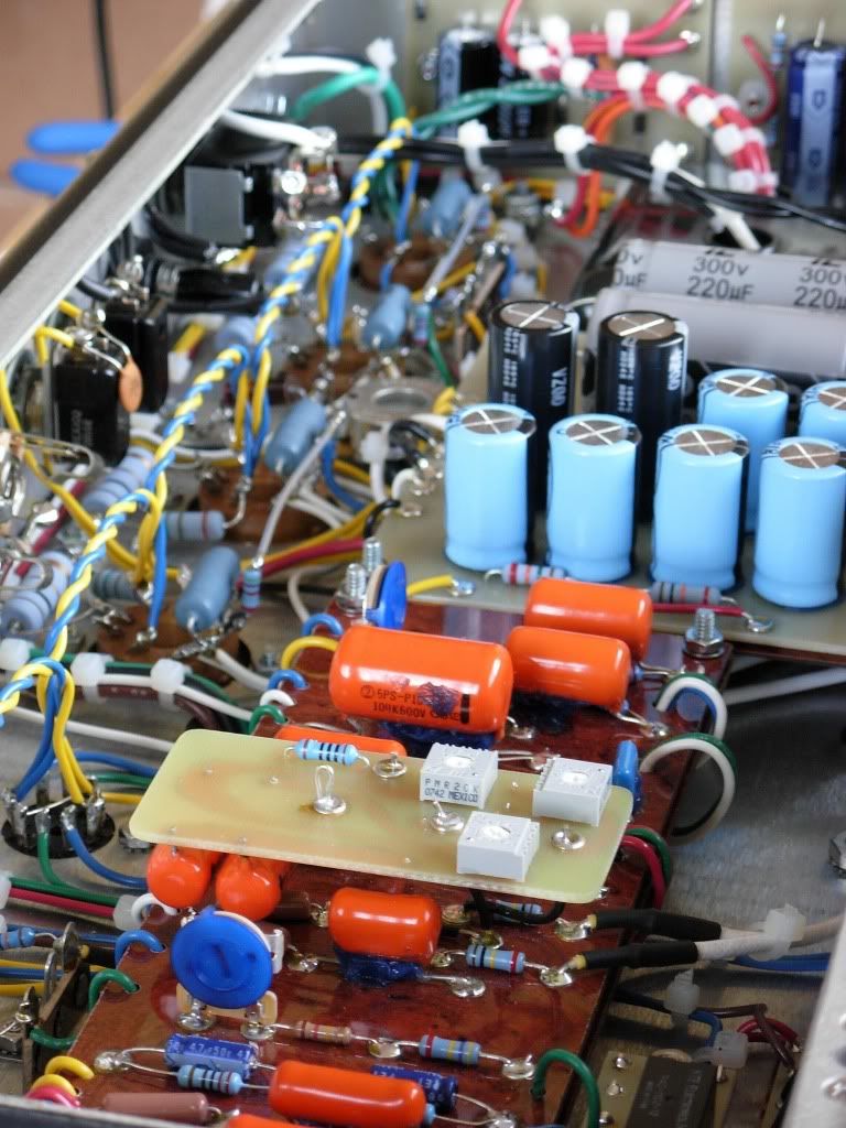
-The two .022uF HRM caps should be oriented horizontally and not vertically as in the layout (see pic below)
-The 100R resistor on the HRM board is labeled 33K.
-Heater resistors should be 150 Ohms.
-Mid pot taper should be Log.
-Pre-OD trimmer resistor should be 120K.
-OD trimmer 100K.
-Shouldn’t the 91K resistor on the layout be 100K?
-Also, the OD1 coupler should be .001uF, no?
-Relay power is V doubler in layout, should be 12V @ 450mA PT into FWR.
-Remove two 1N4007 and their .01uF snubbers on the main PT’s secondaries.
[IMG:768:1024]http://i205.photobucket.com/albums/bb17 ... RMCaps.jpg[/img]
Complete Bluesmaster Layout
Moderators: pompeiisneaks, Colossal
-
UltraHookedOnPhonix

- Posts: 414
- Joined: Thu Dec 15, 2005 9:32 pm
- Location: Dumbleland
Re: Complete Bluesmaster Layout
UHOP.. AFAIK
The OD entrance network IMHO should be set pretty low. 22K to 24K to ground. I used a 50K pot on the back and a 180K resistor to feed it. 100K is for me pretty worthless IMHO. Amp loses it's D-character with the setting too high. 50K pot for me seemed right and in this case the 180K should be used..IMHO
Why I went there!!.. If the real ones had 100k then we should label the pot 100k ..the # on the trimmer reads 1353300
In the pics of the real one I have there are snubbers on the HV diodes..
Thanks for looking over the layout..I'll redo the rest..
Till tomorrow
Tony
You do not have the required permissions to view the files attached to this post.
Last edited by talbany on Fri Oct 29, 2010 4:36 am, edited 12 times in total.
" The psychics on my bench is the same as Dumble'"
Re: Complete Bluesmaster Layout
The 100R seems to be in the right location, 33K as a slope, 100R to lift the mid off ground.UltraHookedOnPhonix wrote:Nice layout Tony!
Some stuff I noticed:
-The two .022uF HRM caps should be oriented horizontally and not vertically as in the layout (see pic below)
-The 100R resistor on the HRM board is labeled 33K.
All the mid pots I've seen on schems have been linear, I used linear and it's working as expected.-Heater resistors should be 150 Ohms.
-Mid pot taper should be Log.
Maybe I should change mine, I have 180K-Pre-OD trimmer resistor should be 120K.
Or a tail to ground like the HRM. I've seen that in schems and the range measure fine in mine.-OD trimmer 100K.
-Shouldn’t the 91K resistor on the layout be 100K?
I tried .002 and .001, yep, .001 just has a clearer smoother OD-Also, the OD1 coupler should be .001uF, no?
I'll attach mine before installing it. Should help.-Relay power is V doubler in layout, should be 12V @ 450mA PT into FWR.
Really? mine looks exactly like this. was the one I was reading wrong.-Remove two 1N4007 and their .01uF snubbers on the main PT’s secondaries.
You do not have the required permissions to view the files attached to this post.
Re: Complete Bluesmaster Layout
Left 100R heater resistor on pin 8 instead of pin 7.
Tom
Don't let that smoke out!
Don't let that smoke out!
-
UltraHookedOnPhonix
- Posts: 414
- Joined: Thu Dec 15, 2005 9:32 pm
- Location: Dumbleland
Re: Complete Bluesmaster Layout
I should have made myself clearer about the diode snubbs. Remove two of the diodes and their "respective" snubberstalbany wrote:UHOP.. AFAIK
The OD entrance network IMHO should be set pretty low. 22K to 24K to ground. I used a 50K pot on the back and a 180K resistor to feed it. 100K is for me pretty worthless IMHO. Amp loses it's D-character with the setting too high. 50K pot for me seemed right and in this case the 180K should be used..IMHO
Why I went there!!.. If the real ones had 100k then we should label the pot 100k ..the # on the trimmer reads 1353300
In the pics of the real one I have there are snubbers on the HV diodes..
Thanks for looking over the layout..I'll redo the rest..
Till tomorrow
Tony
Cool, the reason I used 120K feeding 100K OD trimmer is because there were two schems posted a while back supposedly from the real deal. Also, I took it as gospel when Dogears posted this:
"The low gain network is indeed in some HRM Dumbles. I have pictorial de-gooped proof. Also, the amp I measured had the trimmer set to 26K to ground. The Bluesmaster has a deviation on this theme. Same total load but with a 100K trimmer. 470K into 120K into 100K trimmer. No 47pf cap I believe. Trimmer in the BM I was in had 41K to ground at the trimmer. I think the additional gain is why no 47pf. No 47pf alters the bass response to my ears."
-
UltraHookedOnPhonix
- Posts: 414
- Joined: Thu Dec 15, 2005 9:32 pm
- Location: Dumbleland
Re: Complete Bluesmaster Layout
Yes, you describe the functions correctly of the 100R and 33K but they are not shown correctly on the layout. Beside the 100R resistor it reads 33K, which should be the resistor just under the middle eyelet on the HRM board (placed on the underside of the board).Bob-I wrote:The 100R seems to be in the right location, 33K as a slope, 100R to lift the mid off ground.UltraHookedOnPhonix wrote:Nice layout Tony!
Some stuff I noticed:
-The two .022uF HRM caps should be oriented horizontally and not vertically as in the layout (see pic below)
-The 100R resistor on the HRM board is labeled 33K.
All the mid pots I've seen on schems have been linear, I used linear and it's working as expected.-Heater resistors should be 150 Ohms.
-Mid pot taper should be Log.
Maybe I should change mine, I have 180K-Pre-OD trimmer resistor should be 120K.
Or a tail to ground like the HRM. I've seen that in schems and the range measure fine in mine.-OD trimmer 100K.
-Shouldn’t the 91K resistor on the layout be 100K?
I tried .002 and .001, yep, .001 just has a clearer smoother OD-Also, the OD1 coupler should be .001uF, no?
I'll attach mine before installing it. Should help.-Relay power is V doubler in layout, should be 12V @ 450mA PT into FWR.
Really? mine looks exactly like this. was the one I was reading wrong.-Remove two 1N4007 and their .01uF snubbers on the main PT’s secondaries.
I didn't know that about the mid pot. Thought they were suppose to be log in the BM. Hmmm...
Yeah, the HT rectifier setup should look like the pic Tony posted. 4 1N4007 (2 per secondary) with .01uF bypass snubbers.
Re: Complete Bluesmaster Layout
Thanks a lot! Looks fantastic! 
One question (Sorry, I'm sure it has been discussed before, I just couldn't find any information): why are two 5W resistors in parallel needed for the ps dropping string?
Peace,
Markus
One question (Sorry, I'm sure it has been discussed before, I just couldn't find any information): why are two 5W resistors in parallel needed for the ps dropping string?
Peace,
Markus
Re: Complete Bluesmaster Layout
While we're at it, Scott set the OD and HRM trimmers on my Bluesmaster and I couldn't be happier with the results. Here's his post on the settings.
I tweaked the hrm stack and trigger to smooth things. He had the stack set more for what a skyline hrm would want. I settled on mids of 4.45k and not the 10k he had. Bass down to 73k from 500k. Treble about 40% up. Trigger at 20k to ground. He was at 24k.
Re: Complete Bluesmaster Layout
Great work Tony! Should'nt the treble pot be 250kA? Also, the bypass cap on v2b is lowered to 1uf on mdroberts schemo. Important?
Thanks again for your great work.
Thanks again for your great work.
Re: Complete Bluesmaster Layout
OK!!.. Thanks all for helping out.. I revised the Relay supply to that of the real thing..
Relay supply is 6v taken from 6-0 Radio Shack into FWB filtered before the regulator and after 1000uf
The HV rectifier/bias board is again right off the real deal...Rev 3 now up
Thanks for the input.. But isn't the treble pot a 2-35 special taper Audio.. These are the ones used in all the various generations.. Correct me if I am seeing things..
According to someone who has been inside the amp the 1uf is wrong and the actual value is 4.7uf..
Thanks again all who looked it over.. getting closer
Tony
Relay supply is 6v taken from 6-0 Radio Shack into FWB filtered before the regulator and after 1000uf
The HV rectifier/bias board is again right off the real deal...Rev 3 now up
DocGreat work Tony! Should'nt the treble pot be 250kA? Also, the bypass cap on v2b is lowered to 1uf on mdroberts schemo. Important?
Thanks again for your great work.
Thanks for the input.. But isn't the treble pot a 2-35 special taper Audio.. These are the ones used in all the various generations.. Correct me if I am seeing things..
According to someone who has been inside the amp the 1uf is wrong and the actual value is 4.7uf..
Thanks again all who looked it over.. getting closer
Tony

Re: Complete Bluesmaster Layout
Great job Tony, Your killing me looks like 3 amp builds this year.
Markus, The reason for the two 6k8 5 watt resistors in parallel no such value 3k4 in 5 watts.
I have never used a TF130 magic parts power transformer might have a high B+
I would be interested in a voltage chart.
Thank you, Steve.
Markus, The reason for the two 6k8 5 watt resistors in parallel no such value 3k4 in 5 watts.
I have never used a TF130 magic parts power transformer might have a high B+
I would be interested in a voltage chart.
Thank you, Steve.
Re: Complete Bluesmaster Layout
Steve/ Markus
The real deal has the 2 parallel WW just like the layout.. BUT I cannot make out the values on them so this is a guess and I took them from the schematic that was posted a while back says 3K.. To let everyone know!!
Thanks
Tony
The real deal has the 2 parallel WW just like the layout.. BUT I cannot make out the values on them so this is a guess and I took them from the schematic that was posted a while back says 3K.. To let everyone know!!
Thanks
Tony
You do not have the required permissions to view the files attached to this post.
" The psychics on my bench is the same as Dumble'"
-
mdroberts1243

- Posts: 287
- Joined: Sat Apr 07, 2007 6:59 pm
- Location: Ottawa, Canada
- Contact:
Re: Complete Bluesmaster Layout
I think Scott commented at some point that all the cathode bypass caps are 4.7uF on the real BM he has seen... I'll be updating a version of the schematic to align with Tony's layout once the dust settles.Dr d wrote:Great work Tony! Should'nt the treble pot be 250kA? Also, the bypass cap on v2b is lowered to 1uf on mdroberts schemo. Important?
Thanks again for your great work.
-mark.
My tube blog & link directory: http://tubenexus.com
Cause & Effect Pedals FET Dream and Dumble Style Chassis
My tube blog & link directory: http://tubenexus.com
Cause & Effect Pedals FET Dream and Dumble Style Chassis
Re: Complete Bluesmaster Layout
Hi Mark, thanks for the input and for your original schemo which I used recently.....it made a great sounding amp! So far the only things I might change are some of the bright caps. thanks again.
BM Tweeks
I built a 50W version from the mdroberts1243 schematic. Only issue I had was the amp was excessively bass heavy. Great for high gain and heavy metal (my son loved it), but not the sound I was looking for. So, I decreased the bass pot to 250K and the HRM bass to 500K. Now the amp really sings! I used a 0.002uF coupling cap on OD1, which may account for some of the excessive bass. Bob-I (see above) likes a 0.001uF cap here. I have the OD entrance pot set to 15K.
Attached is a BOM. Parts are for the old style power supply, not the one depicted in the schematic. I can also supply faceplate files for BNP Lasers.
Kudos to Tony for the awesome layout!
Attached is a BOM. Parts are for the old style power supply, not the one depicted in the schematic. I can also supply faceplate files for BNP Lasers.
Kudos to Tony for the awesome layout!
You do not have the required permissions to view the files attached to this post.