So, the screen R's and V's seem fine. Re the resistor values for the bias circuit, don't worry about reducing the upper leg of the divider to 7K5, you can leave the 10K that is in there alone. The reduction to 7K5 was to get some more range on the cold side, which you don't need.
Andy, I used 70% max Pa just to get an idea of where this thing is sitting now. Once the adjustable bias is in and working it can be tweaked to taste. Also, the OP said he measured Ia using the OT shunt method, so that is anode current alone. Anode voltage is over spec... some caution may be wise, and besides I don't want to get blamed for toasting a set of tubes, either! ;^)
Cheers,
MPM
Adding Bias Adjustment Pot
Moderators: pompeiisneaks, Colossal
-
martin manning

- Posts: 14308
- Joined: Sun Jul 06, 2008 12:43 am
- Location: 39°06' N 84°30' W

Join the party
ok I am on a 6G4 and in a very similar moment. All my resistors are to spec within 10%. Voltages all check to within 10%. I am using 12AX7's instead of 7025 but the other tubes are the normal compliment, GZ34, 6L6GC. Amp sounds fine, viabrato works well. The Bias readings are similar to RightLurker , 20 & 22 ma. I have 1R 1w resistor from pin 8 to ground. The only anomaly in the amp is the use of 2 50uf150 caps at the Bias board instead of 8uf 150. Tubes are checked out in another amp and they are to spec. Bias resistors are per schematic 10k & 56K. i am waiting on a trimmer to implement Martins suggestion for the bias pot set-up. With all these values more or less in line why is the Bias so low?

Re: Adding Bias Adjustment Pot
Just curious how does your bias point look on a scope? Aligator clip in a pot adjust your bias. meter the pot replace with a resistor or drill a hole and mount a pot.
The 12ax7 is a 7025 the only difference is mil spec or low noise.
If all voltages test good then just adjust the bias until your tone comes to life. 70% is just a starting reference get it there and finish by ear just make sure you aren't red plating the output tubes.
The 12ax7 is a 7025 the only difference is mil spec or low noise.
If all voltages test good then just adjust the bias until your tone comes to life. 70% is just a starting reference get it there and finish by ear just make sure you aren't red plating the output tubes.
My Daughter Build Stone Henge
Scope
Yah, I wish I could learn about scopes and their use, soon. The tone is great on this amp. I will put the trimmer in. I was just curious as to why the tubes would be at these low readings with the other parameters being so close to spec.
-
Andy Le Blanc
- Posts: 2582
- Joined: Sat Dec 22, 2007 1:16 am
- Location: central Maine
Re: Adding Bias Adjustment Pot
There's several free software scopes online, You've got to be careful with
a scope and the bias.
It gives you something to look at but doesn't give you a dissipation figure.
low bias,
can you post a pict. or scheme of what you have going on.
The cap value should be ok. What R do you have in series in the circuit.
a scope and the bias.
It gives you something to look at but doesn't give you a dissipation figure.
low bias,
can you post a pict. or scheme of what you have going on.
The cap value should be ok. What R do you have in series in the circuit.
lazymaryamps
Re: Adding Bias Adjustment Pot
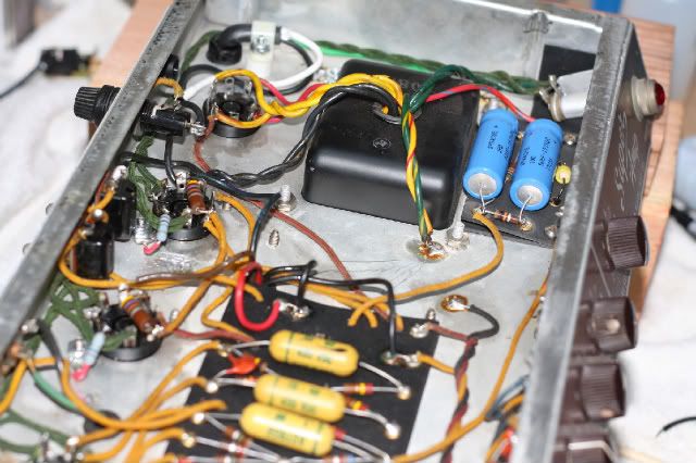
Its a stock 6G4 except for the 1R to ground for bias reads and the 50uf/150 caps on the bias board.
R in series - 10k 56k to the dual 220k network
[IMG:640:426]http://i260.photobucket.com/albums/ii9/ ... 5360-1.jpg[/img]
R in series - 10k 56k to the dual 220k network
[IMG:640:426]http://i260.photobucket.com/albums/ii9/ ... 5360-1.jpg[/img]
Re: Adding Bias Adjustment Pot
the basic scope setup is a tone source selectable ( 100hz, 1k, 10k, etc) of sine wave plugged into the input of the amp... out of the amp to a dummy load ( you don't want to listen to a blazing speaker!!!) tap off the dummy load to the scope. as you turn up the volume knob you will see the wave form develope ( set the bias to the highest "-" negative number -33 being higher then -32.... etc. now bring up the bias slowly... -33, -32, -31... and you will begin to see the notch start to smooth out... you do not want the notch to completely dissapear... reading your multi meter .... stop around 70% for your tube dissapation. flip standby plug in a speaker and play... how does it sound... adjust to taste. probably +/- 1Ma from where you are will do it. (THERE IS MORE TO IT BUT BASICALLY THAT IS THE SETUP)
I like the scope to visually see the X-over point but lately I've found the Compu-Bias to be the quickest and most musical way to bias. I can view up to 4 tubes at the same time, using two units. Then if any one tube is acting up I can shutdown or adjust accordingly. The readout gives Ma and wattage per tube along with a recommendation for a starting point for each tube type on the housing. not saying it's the best or only way to bias... just that it is quick, does the math and gives a visual reading of all tubes in real time. I get it in the ball park. play listen adjust, play listen adjust, all the while making sure the tubes are not redplating and my limits are not exceeded.
I like the scope to visually see the X-over point but lately I've found the Compu-Bias to be the quickest and most musical way to bias. I can view up to 4 tubes at the same time, using two units. Then if any one tube is acting up I can shutdown or adjust accordingly. The readout gives Ma and wattage per tube along with a recommendation for a starting point for each tube type on the housing. not saying it's the best or only way to bias... just that it is quick, does the math and gives a visual reading of all tubes in real time. I get it in the ball park. play listen adjust, play listen adjust, all the while making sure the tubes are not redplating and my limits are not exceeded.
My Daughter Build Stone Henge
-
martin manning
- Posts: 14308
- Joined: Sun Jul 06, 2008 12:43 am
- Location: 39°06' N 84°30' W
Re: Adding Bias Adjustment Pot
So for you guys who have seen a lot of old Fenders, does the bias voltage required for new production tubes tend to be less negative than indicated on the original schematics? Seems like that is a trend.
Granted B+ is probably higher by 10% or so today, unless some type of line voltage reduction is done, but I'd think all the voltages in the circuit would scale, more or less.
MPM
Granted B+ is probably higher by 10% or so today, unless some type of line voltage reduction is done, but I'd think all the voltages in the circuit would scale, more or less.
MPM
Last edited by martin manning on Tue Jan 26, 2010 1:37 am, edited 1 time in total.
-
Andy Le Blanc
- Posts: 2582
- Joined: Sat Dec 22, 2007 1:16 am
- Location: central Maine
Re: Adding Bias Adjustment Pot
The voltages in old schematics were there so the average smoe could check it
with a simple volt/ohm meter without blowing it up.
The light bulb, let alone electronics isn't but a hundred years old, and the
term "American consumer" precludes any intelligence, use the plate dissipation figure in watts.
where are the tubes at for dissipation?
lift the 10k and measure it. carbon comps can drift.
If you had a very large uf value cap it might cause that issue but those should be good.
check the diode.
lazymaryamps
Up and running
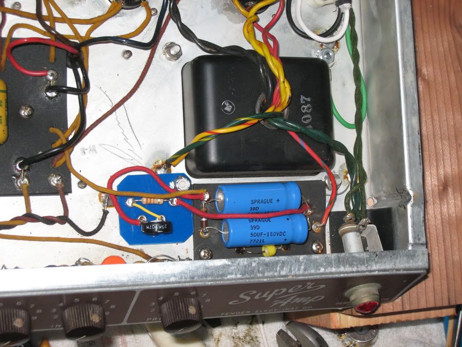
Ok, thanks Martin, Tony, Andy et all....Its working very well. I know its a bit unconventional but i can pull the board and replace the 56k in minutes if I every wanted to get back to vintage spec> But this amp is family bound. The 33k R is taking me to about 35ma limit so if I wanted to crank further I might go for a lower R on the mini board. Negative voltage was a new concept so it took me a while to fathom it. Oh.. the small board has a backing to insulate the connections.
[IMG 1258]http://i260.photobucket.com/albums/ii9/ ... -schem.jpg[/img]
[IMG:900:675]http://i260.photobucket.com/albums/ii9/ ... nstall.jpg[/img]
[IMG
 1258]http://i260.photobucket.com/albums/ii9/ ... -schem.jpg[/img]
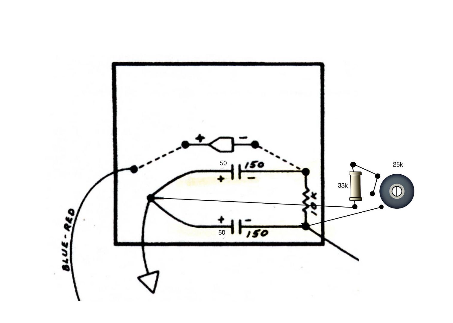
[IMG:900:675]http://i260.photobucket.com/albums/ii9/ ... nstall.jpg[/img]
-
RightLurker
- Posts: 91
- Joined: Sat Dec 19, 2009 3:00 pm
Re: Adding Bias Adjustment Pot
I finally found the time to install the 27K resistor and 50K trim pot in accordance with Martin's bottom right-hand layout diagram. It works just fine - thanks, Martin. Using these component values, however, the least amount of current I can get running through the tubes is about 13 milliamps, and the maximum amount of current is 34.8 milliamps. Running at 34.8 milliamps, the plate voltage is 458 volts, which I calculate to puts the idling plate dissipation at 15.9 watts.
The tubes are new Tung Sol 5881s. I am concerned because the Tubestore website says the maximum plate voltage for the Tung Sol 5881s is 400 volts. It does say that the tubes can be used in a tube rectified amp running higher plate voltages without issue, and the amp in question is a 6G6 Bassman with a 5AR4 rectifier. The tubes are 23 watt tubes, so I should be okay there - I make 15.9 watts to be just short of 70% of 23 watts.
Should I change the 27K resistor to try and get more current (and less plate voltage) on the tubes, or would I be better off I substituting 6L6GCs for the 5881s? Thanks in advance.
-
martin manning
- Posts: 14308
- Joined: Sun Jul 06, 2008 12:43 am
- Location: 39°06' N 84°30' W
Re: Adding Bias Adjustment Pot
You're measuring plate current alone right (OT shunt)? Then you are right on the money for the 70% rule, and you *should* be ok with the higher plate voltage since you are running a tube rectifier. If you run the current up, the plate voltage may come down, but the product of the two (power) will increase, so I'd stay where you are. As far as changing to 6L6, I think that becomes a question of which tone you like better.RightLurker wrote:The tubes are 23 watt tubes, so I should be okay there - I make 15.9 watts to be just short of 70% of 23 watts.
Should I change the 27K resistor to try and get more current (and less plate voltage) on the tubes, or would I be better off I substituting 6L6GCs for the 5881s? Thanks in advance.
MPM
PS, If you want to get the trimmer back in the middle of its range, and get more adjustment on the "hot" side, you might better change the 10K fixed resistor to a 15K. Keeping the total resistance to ground around the original 66K will keep the current flowing through that path in check.
Re: Adding Bias Adjustment Pot
Up the 27k resistor to 33-39kRightLurker wrote:I finally found the time to install the 27K resistor and 50K trim pot in accordance with Martin's bottom right-hand layout diagram. It works just fine - thanks, Martin. Using these component values, however, the least amount of current I can get running through the tubes is about 13 milliamps, and the maximum amount of current is 34.8 milliamps. Running at 34.8 milliamps, the plate voltage is 458 volts, which I calculate to puts the idling plate dissipation at 15.9 watts.
The tubes are new Tung Sol 5881s. I am concerned because the Tubestore website says the maximum plate voltage for the Tung Sol 5881s is 400 volts. It does say that the tubes can be used in a tube rectified amp running higher plate voltages without issue, and the amp in question is a 6G6 Bassman with a 5AR4 rectifier. The tubes are 23 watt tubes, so I should be okay there - I make 15.9 watts to be just short of 70% of 23 watts.
Should I change the 27K resistor to try and get more current (and less plate voltage) on the tubes, or would I be better off I substituting 6L6GCs for the 5881s? Thanks in advance.
-
martin manning
- Posts: 14308
- Joined: Sun Jul 06, 2008 12:43 am
- Location: 39°06' N 84°30' W
Re: Adding Bias Adjustment Pot
If the goal is to center the trimmer and/or shift the range to the hotter side, RL needs to decrease the 27K ground leg resistance or increase the supply leg resistance.tubeswell wrote:Up the 27k resistor to 33-39k
MPM
Re: Adding Bias Adjustment Pot
really good information in here...I'm reading and rereading this posts in an attempt to do the same to a Magnatone M15 I'm resurrecting. This is an unusual amp in that it's essentially two complete amps in one, to enable stereo vibrato and other silly (but undeniably cool-sounding) features. If that weren't enough, each amp uses a pair of 7189As, which are long out of production, expensive, and very difficult to find stable substutites for. So implementing an adjustable bias supply seems like a worthwhile precaution.
I'll attach a schematic, but in general the bias circuit is not far from a "standard" fender circuit, except that in this case the series resistor is of a higher value (22k) than the resistor to ground (12k).
I'm guessing that adding a 10k linear pot between the two resistors (as per MP Manning's helpful diagram), and reducing the value of the series resistor by 25% or so, should get me in the ballpark, no?
Moreover, is there any implication to the power supply if I add a single bias adjustment pot for each pair of output tubes? I don't trust that my 7189As are actually a matched quad, and frankly it doesn't seem to matter much if they are or not, as there are two discrete amps working here.
Any insights you all have, I'm all ears!
You do not have the required permissions to view the files attached to this post.