
FET Input in a box! For all you D-amp owners that want a switchable FET circuit. I’ve designed it to include some extra goodies like switchable input impedance and the ability to select a buffered output or effected/amplified output.
The B+5 power supply node in ODS amps hover around 303V-323V, this Voltage is then reduced by a 150K/8.2K Voltage divider, which supplies the FET circuit with 15.7V-16.7V. A simple way of getting in that ballpark is to simply use an 18VDC source (from a Dunlop ECB-004 etc.) and drop the Voltage with a 3.9K resistor. Then, simply use a trimmer in place of the FET’s Source resistor to calibrate the Drain’s Voltage between 10V-11V. Replace trimmer with closest value resistor. Voltages of more than 12V will slightly decrease the volume whereas Voltages lower than 2.45V will cut off the signal. Also, note that the lower the FET’s Source resistance, the higher the Drain Voltage.
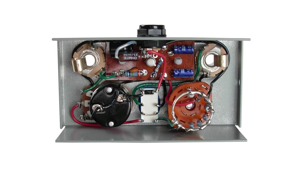
The standard 3.3M input resistance value will brighten up the signal in a significant way, almost like a treble booster. So, if you fancy a FET amplifier with a flatter frequency response, make it switchable! I used a 1pol-7pos rotary switch with values ranging from: 68K, 100K, 150K, 220K, 475K, 1M and 3.3M. You’ll hear a very slight treble increase even with a lower value like 100K. Naturally, you’ll also notice the noise decrease slightly as you decrease the input impedance. This tames (albeit marginally) the familiar ssssshhhhhhh-sound associated with using the FET input on the OD channel.
The buffered output option is really nice if you need to drive long cables or maintain you’re high-end. Cool thing is, the input Z is still switchable. The way the output switching works is that in buffer mode (through the relay’s normally closed contacts), the signal is taken from the Source resistor’s 4.7uF bypass cap where it now acts as an output coupling capacitor. This is the non-inverting output. When the SPST switch is closed on the back of the volume pot, this grounds pin 16 of the relay’s coil, energizing the relay which switches state. Now, it’s in “effect mode” and amplifies the signal from the inverting output. Conveniently enough, Fujitsu makes an 18VDC signal-switching relay, Mouser part#: 817-RA-18W-K (not so many left in stock though).
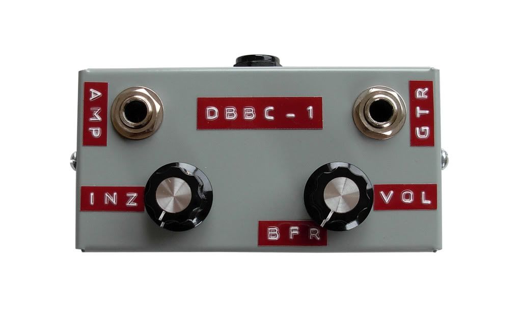
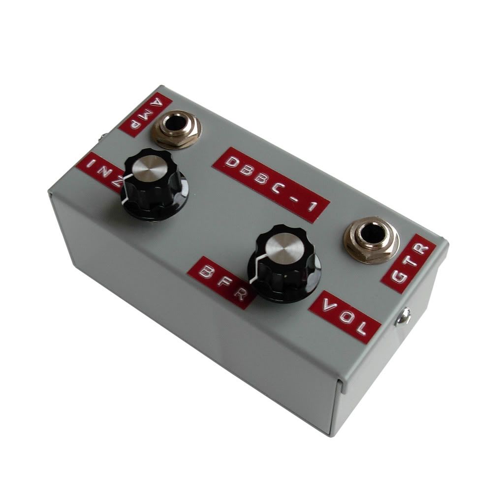
Below is the schematic with Voltages and some pictures of my build which has been built to resemble the Dumble BBC-1 (https://tubeamparchive.com/viewtopic.ph ... light=bbc1). Note: Voltages shown are with a NTE452 FET and I've left off the bypass and rotary switch wiring. On it’s own this FET circuit gives a great clean boost and it can prove to be a useful front end for amps other than the ODS as well.
Have Fun!
[IMG:777:1024]http://i205.photobucket.com/albums/bb17 ... ematic.jpg[/img]
[IMG
 616]http://i205.photobucket.com/albums/bb17 ... 1Front.jpg[/img]
[IMG
 1024]http://i205.photobucket.com/albums/bb17 ... -1Side.jpg[/img]
[IMG
616]http://i205.photobucket.com/albums/bb17 ... -1Guts.jpg[/img]
