
Hi, just got my kit from Otto, nice shape. On setting the variable lugs, I get that some light sanding on the resistor surface and the inside of the lug is a good idea. What about the the degree of sanding on the variable resistor, so as to be able to move the lugs and get an accurate ohm reading. I suppose one sets them and then reads and fidgets until they are close to the recommended readings.
Ange
DIY Airbrake...
Moderators: pompeiisneaks, Colossal
Checking my Airbrake. ohm readings
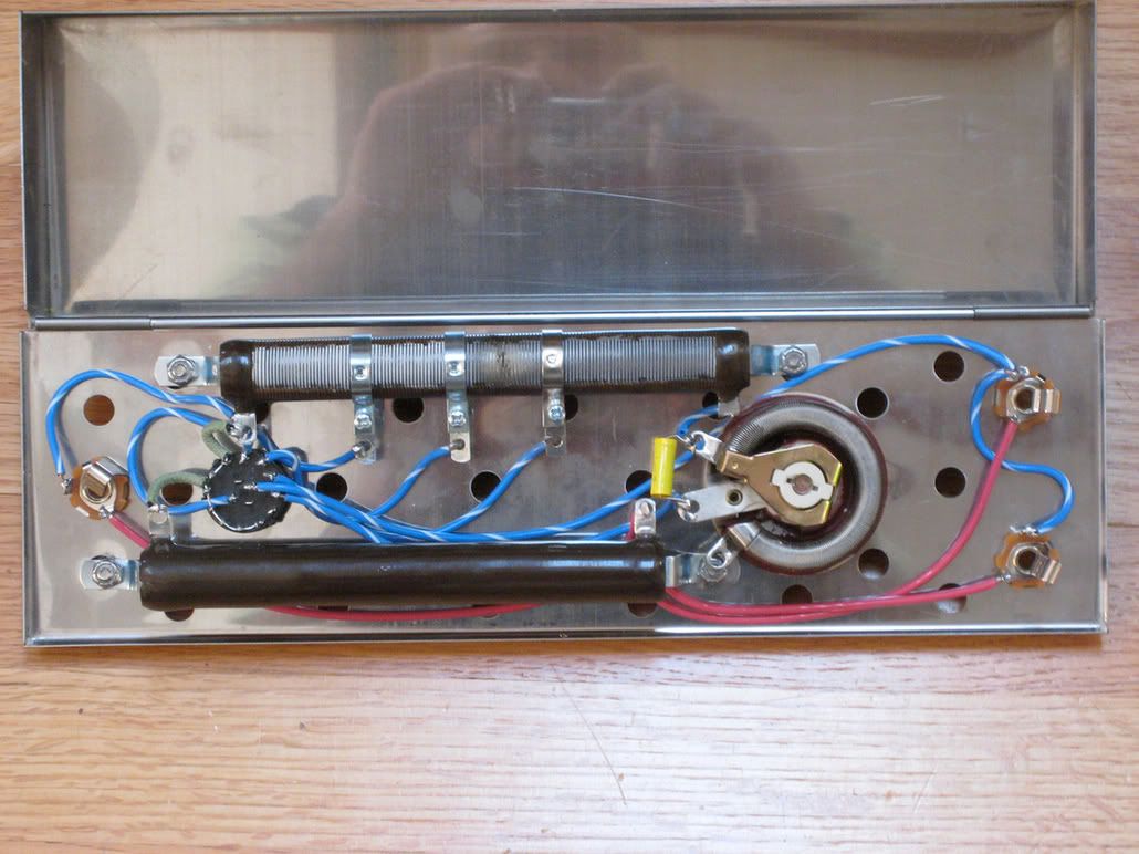
New airbrake build, works great.
best Ange
[IMG 772]http://i260.photobucket.com/albums/ii9/ ... rbrake.jpg[/img]
best Ange
[IMG
 772]http://i260.photobucket.com/albums/ii9/ ... rbrake.jpg[/img]
Last edited by angelodp on Wed Apr 15, 2009 6:13 am, edited 1 time in total.
Re: DIY Airbrake...
Ange,
It almost looks like your adjustable resistor is burnt right in the middle?
It almost looks like your adjustable resistor is burnt right in the middle?
Tom
Don't let that smoke out!
Don't let that smoke out!

Re: DIY Airbrake...
Lonely raven sumed it up early in this thread
I haven't built this, but I would figure you just measure with your DMM.
Stab the Black pole into the end, and the red pole into one of the sliding pieces and slide up and down till you read what you want to read. Lock it down and DONE.
I haven't built this, but I would figure you just measure with your DMM.
Stab the Black pole into the end, and the red pole into one of the sliding pieces and slide up and down till you read what you want to read. Lock it down and DONE.
Corrected readings
Ok I have new readings that are tip to tip. Box is done, I have short cord in the input and the output and I am reading the six position switch. Tip to Tip.
1. 01.0 ohms
2. 01.2
3. 6.5 ohms
4. 11.3 ohms
5. 16.3 ohms
6. Rheostat position - Rheostat goes from 25 ohms to 170 ohms
could anyone with the rheostat type confirm these readings.
ange
1. 01.0 ohms
2. 01.2
3. 6.5 ohms
4. 11.3 ohms
5. 16.3 ohms
6. Rheostat position - Rheostat goes from 25 ohms to 170 ohms
could anyone with the rheostat type confirm these readings.
ange
Last edited by angelodp on Wed Apr 15, 2009 9:40 pm, edited 1 time in total.
thanks got it
Thanks M Fowler, for this tidbit. I plugged it into my Rocket and whoha !! Its a done deal and I love it. Even the rheostat is usable, although only for dire circumstances ( wife looking cross into the room ). Love the main clicks on my Rocket and it allows me to Dime the amp and get that great rocket rumble.
Best Ange
PS thanks OTTO for a great kit and good instructions.
I pulled one of my Lorlin switches and see the numbering problem you're having. It's very odd that the numbers don't even match front to back isn't it? Attached is a new layout with the numbers matching the Lorlin switch as you're looking at the terminal end. It's the physical location of the pins that matters not the numbers. With the switch in it's fully CC position (which on the control faceplate is "0") terminal C is connected to terminal 7 which is jumped to terminal 8. We are really only using 5 positions of the switch so in the first two positions the resistor is bypassed. 0 and 1 positions are identical. Positions 2 thru 4 are 6 ohms, 11 ohms and 16 ohms respectively. In the bedroom position, you have the 150 ohm rheostat in series with the full 25 ohms of the multitap power resistor. I hope this helps.
**Just an added note, it seems that this is perhaps the most important bit of info for any new builders as the fact that positions 0 & 1 are bypassed and then the resistance kicks in on 2-4, with 5 as the rheostat. So although its a six position switch we are counting from 0-5. That was confusing for a while.
Re: DIY Airbrake...
I was snooping around the web today and stumbled across this.
If it is old news, disregard, but I thought some of you might find it interesting.
--------------------------------------------------------------------------------------
RE: DR Z Airbrake comments by its designer, Ken Fischer
Holiday Greetings from Ken Fischer, DR Z & Komet Amplification!
I just received this discussion thread regarding power attenuators via fax. Since I do not have a computer or Internet access, l have asked PinkStrat [Dean] to add some commentary on the Airbrake attenuator(s). First, I feel it's important to add that the Airbrake attenuator has been on the market for 17 years...longer than any other attenuator in production that I am aware of. When the Airbrake first became available, you had to own a Trainwreck amp in order to purchase one. Since I serviced all of my own amplifiers myself, I have used [and continue to use] the Airbrake attenuator myself. If there were any problems with this attenuator harming amplifiers, transformers, tubes or speakers, I would have become aware of these issues and would have therefore modified, redesigned or discontinued building the Airbrake attenuators.
The Airbrake was originally [and still is designed] as a 100 watt device. However, when using a power attenuator, some of the power is dissipated in the attenuator and some is dissipated by the speakers. Also, due to the internal electronic design of the Airbrake, as you select a higher level of attenuation the wattage rating of the unit also increases up to a maximum of 200 watts.
This makes the Airbrake attenuator perfectly SAFE for high powered 100 watt amplifiers, such as the 1959 Marshall & DR103 HiWatt heads. On these high powered British amps, due to their unique transformer designs, when using a single 16 ohm cabinet I recommend setting the impedance selector to 8 ohms when using the first two levels of attenuation. We also make this recommendation for any amp using EL-84 type output tubes. The reason for this is simple; when used this way, this will result in a reduction of the current flowing through the output tubes at FULL POWER.
Technical observations:
There was mention in this discussion thread of other attenuators being constant impedance devices. This would actually make these attenuators harder on the amplifier than if used with just a speaker load. Loudspeakers are NOT constant impedance devices. Anybody who has done frequency versus impedance studies on various speakers (in various cabinet configurations) will find that speaker impedance varies enormously. First with frequency and wave shapes and additionally with multiple frequencies and complex wave shapes as generated by a guitar amp under distortion. For example, a 16 ohm standard 4-12 Marshall cabinet can be as low as 10 ohms as the frequency approaches DC & over 30 ohms at some of the higher frequency harmonics generated by the guitar under distortion.
I've personally done these studies at Ampeg in the 60s & at Trainwreck during the 80s. FYI--another feature of guitar loudspeakers is when the cones are set in motion by a signal, the speaker also generates its own voltage as the mechanical suspension pulls the cone back to its neutral position (at rest). The speakers also generate "overshoot voltages" and other various voltages during operation. These voltages (known as "kickback" voltages) are reflected back to the primary of the output transformer to the power tubes. In addition, if the amp is equipped with a feedback loop (which most amps have), these "kickback" voltages are also applied to the feedback loop via the speakers and output transformer secondary. If you take a speaker and cut the cone out & then glue the voice coil into the gap [so that it will not move] these kickback voltages are no longer present. Also, there is no cone inertia for the output stage to overcome (which affects the way the output stage responds). If you do a frequency versus impedance graph of this deconed, frozen voice coil "speaker," you will have a radically altered graph compared to when the speaker was functional. In effect, you no longer have a speaker as a load but an inductive resistor... As for how the Airbrake attenuator handles both 4, 8 & 16 ohm loads-- it's magic!
Rock On'
Ken
Tom
Don't let that smoke out!
Don't let that smoke out!
Schematics
Hi! I would be grateful for a copy of the schematics/layout of this clone. I saw the post with the fan drawn out but i dont know if that's some kind of modded version or not.
junkAThumbugvisualsDOTcom
I own a something around 20watt supro clone that i wish i could strangle down to bedroom levels. Should i go with the original layout or do you guys recommend any mods, cause it's not an amp with very high watts..
If it's dumb questions, excuse me I'm just getting into the whole diy electronics.
Thanks!
Re: DIY Airbrake...
Structo, that is interesting.Structo wrote: On these high powered British amps, due to their unique transformer designs, when using a single 16 ohm cabinet I recommend setting the impedance selector to 8 ohms when using the first two levels of attenuation. We also make this recommendation for any amp using EL-84 type output tubes. The reason for this is simple; when used this way, this will result in a reduction of the current flowing through the output tubes at FULL POWER.
Rock On'
Ken
So on an EL84 combo amp that runs on (2) Celestion 16ohm 20 watt speakers in parallel, for an 8 ohm load, does that mean the amp should be set at 4 ohms? Like that is the same ratio Ken said of 8ohm on head, to 16ohm cab for EL84 amps. And what does he mean the first two levels of attenuation for 100 watt Marshalls,, the 2 settings that are the least attenuation, or the 2 setttings of high attenuation where the volume is lowest it will get? Does this apply to 50 watt plexis too? I have a JTM50 with tube recto.

Re: DIY Airbrake...
Hey angelodp, nice work. I still haven't tried mine with my rocket build, but I'm sure it'd be cool. I LOVE the way it interacts with my express build. The best part about it is how it lowers the hiss volume in the express. YEAH!
Re: DIY Airbrake...
Arnqvist
PM sent layout/schematic
Mark
PM sent layout/schematic
Mark
Re: DIY Airbrake...
I don't know anything about airbrakes, I just found that KF article and thought you guys would enjoy it.
I think it is from his Trainwreck Pages.
I think it is from his Trainwreck Pages.
Tom
Don't let that smoke out!
Don't let that smoke out!
Re: DIY Airbrake...
That is OK structo. Perhaps someone else can chime in and clarify for me?