in AWG sizes I had bought 16, but should have bought 20. 20 was way to big. The cable i did use was 16 sized, but it had multiple thin wires instead of one solid wire inside. It is 6.4V 2A so the wire has to sustain 13W without melting, also the chassis gets pretty hot, so it has to be able to take that. I did work the 20 minutes I tested the amp, but for my own reassurance I will change it out with a more sturdy cable.
What I didn't understand about that grounding thing is how to connect it all, is the idea to get the whole circuit in one loop? I can live with a little hum, the way it was before I rewired the tube sockets was actually pretty good. Just a low hum that was not audible when playing guitar.
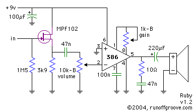
I also have another question, I started studying some other circuits for my tiny pocket amp project. My idea was to try to design it myself, so I started looking at other similar circuits, and read up on amplifier theory and trying to get it all. Then I stumbled across a small amp named "Ruby"
here is the schematic:
[img:385:220]http://runoffgroove.com/ruby.png[/img]
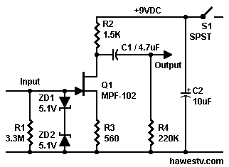
But when I started looking at other circuits based on that transistor, I noticed the transistor was wired differently, how come that is?
Here is another example:
[img:322:235]http://www.hawestv.com/amp_projects/fet ... preamp.png[/img]
By the way these circuits are freakishly similar to the preamp in my amp, except for the tube and high voltage of course. Is it that a preamp is a preamp regardless of components?
DocZ
Help! I tried to recap my amp!
Moderators: pompeiisneaks, Colossal
Re: Help! I tried to recap my amp!
16 ga wire is bigger than 20.
As the numbers go down the diameter goes up.
Generally on a guitar amp you have a few different grounding schemes that will work.
Usually you ground the power supply and it's filter caps near where the power cord comes in.
The earth wire from the ac cord should get it's own ground screw near the inlet and have some slack to the ground wire.
This is in case the power cord gets yanked hard and pulls the hot wire loose, so then you would still have the chassis to earth preventing electrocution.
Then your power supply filter caps should go nearby that.
Some guys like to ground the caps that filter the supply for the preamp tubes up near the input since that is a quieter spot.
All your tone caps, bypass caps and input jack grounds should go to ground over near the input jack.
Without going back to your photos, sometimes there is a bare wire known as a ground buss wire that all the preamp grounds are soldered to.
Sometimes this ground buss is soldered directly to the backs of the pots.
Other times it floats above the pots and short jumpers from the ground lug on the pots get soldered to that.
This ground buss wire should go to a ground screw below the input jack.
You get ground loops when you have several grounding spots and the current travels through the chassis causing a difference in potential, causing the hum. ( that is the simple version)
On a small amp like that, I would ground the big filter caps over by the power cord.
Use star type washers under the lugs and nuts so it bites into the chassis making good contact.
Then run the other grounds from the preamp section to the common ground over by the input jack.
This may be hard to decipher on a point to point amp, but look at it this way, when you figure out how a point to point amp works, an amp based on a eyelet or turret board will be a breeze!
Tom
Don't let that smoke out!
Don't let that smoke out!

Re: Help! I tried to recap my amp!
Tom and I have crossed paths on grounding before and I think we've agreed to disagree. As far as I can tell, there is more than one correct way to do it. I'm not saying there is anything wrong with his advice.
I don't like the ground point over near the inputs, but people claim good results with it. If it were my amp, I would gather all the preamp grounds in this amp and connect them to a single floating point. Floating means a ground lug that is insulated from the chassis (not really grounded, just a gathering point). Then, run a single wire from the floating point to the place where you ground the main filter caps.
This is just another possibility. When you are in there working, having options is a good thing. Eventually, you will see that one is easier to do than the other.
You can eliminate a lot of the hum if you try. You don't need to "live with it" and the amp will be more pleasing without it.
Phil
Re: Help! I tried to recap my amp!
Ok, I think I get what you are saying now.
To explain how things are in my amp:
There are five terminal strips, one of them the entire strip is connected to the center terminal, which again connects to grouhd where the strip is screwed to the chassis. This strip sits behind the tremolo know, it is about 3 - 4" from the screw that I soldered the AC ground wire to. This strip is the grounds for the three filter caps (I don't know if that last one is a "ripple" cap or a filter cap), the OT, the "E" on the PT secondary, the resistor on the left leg of the tremolo knob, and the ground cap on the tone know. The remaining strips have the center terminal connected to ground with a screw to the chassis. The next one sits just under 1.5" from the ground terminal and connects the g2 and p2 cap/resistors of V2 to ground. Next one is 1" above the previous one, and sits straight behind V2, it connects the caps/resistors on the tone circuit and the shield from the reverb wire to ground. Next strip is between V2 and the EL84, about 2" to the side. This has the ground for the V1 cathode cap/resistor, and pin 1 and 2 of the EL84 through a resistor to ground. Next one is straight over it, about 1.5" up. There the other cathode cap/resistor of V1 connects to ground. Last but not least, is straight behind the input jacks. Which handles grounds for the inputs resistors. All the pots have a hole cut out for them on the bottom of the chassis, they are mounted in an angle into that hole so that their backs touch the chassis.
That is about it for grounding in this amp.
BTW. those two pins on the EL84, isn't that first pin an internal connection, does it mean it shouldn't be used like it is used here? Could that be the source of the noise?
DocZ
Re: Help! I tried to recap my amp!
Docz You make me proud
Reading your replay I was smiling. You have learned so much I am proud of you man !!!!!
I'm also proud you're still alive!!!!!
Think, plan, and be smart.... and you will figure this out. Throwing $$ at a problem is never the answer. It might fix it, but the real fix is as its always been... Be smart and figure it out. Then when its fixed - its fixed.
Good luck
Re: Help! I tried to recap my amp!
If each one has a ground to chassis, this is too many. The chassis should not be used as a ground buss, making it part of the circuit. The chassis is there to be a shield from interference.docz wrote: ] There are five terminal strips,
I would keep this strip as the main ground point. You can consider all the lugs as one because they are wired together. If this were mine…things that stay here…the three filter caps (they filter ripple!), the OT, and the E terminal.one of them the entire strip is connected to the center terminal, which again connects to ground where the strip is screwed to the chassis. This strip sits behind the tremolo know, it is about 3 - 4" from the screw that I soldered the AC ground wire to. This strip is the grounds for the three filter caps (I don't know if that last one is a "ripple" cap or a filter cap), the OT, the "E" on the PT secondary, the resistor on the left leg of the tremolo knob, and the ground cap on the tone know.
Remove the resistor from the tremolo pot and the cap from the tone pot. (The pot is inside the amp, the knob is on the outside and helps you turn the pot!). These go somewhere else.
Yes, each of those center lugs is a possible ground point. Don’t use them!The remaining strips have the center terminal connected to ground with a screw to the chassis.
Now it is time to organize how to group the grounds. This is how I do it. Each ground stage ends with a cathode. Past the cathode is the next stage. Because of the simplicity of this amp, and because it is a low gain amp, it isn’t necessary to be too exacting. I had trouble following the rest and cut it from my reply.
1st ground group: V1A has the inputs. Find the grounds from the input jacks. Find the resistor and cathode 1K/30u on the schematic. This is the end of the first stage. Tie these to one ungrounded lug on a terminal strip and mark it as #1.
2nd ground group: Follow the schematic across to V1B (top of the page). There are many grounds going across: .005 cap connected to the 500K pot, 10K resistor, outer lug of the 2nd 500K pot. Tie these to one ungrounded lug on a terminal strip and mark it #2.
3rd ground group: Go to the bottom half of the schematic. Find for V2A the cathode 1K resistor and 30u cap. Tie these to one ungrounded lug on a terminal strip and mark it #3.
4th ground group: Keep going across the page. 1M resistor before the reverb, 1M resistor after the reverb. Tie these to one ungrounded lug on a terminal strip and mark it #4.
5th ground group: Tremolo. For V2B gather the two 1M resistors, and the outer leg of the 250 resistor connected to the pot, and tie these to one ungrounded lug on a terminal strip. Mark it #5.
Run a wire between 1 and 2. From #2 run a wire to the ground point for the 3rd filter cap, the one on the schematic most to the left, near V2B on the schematic.
Run a wire from 3 to 4 to 5. From #5 run a wire to the ground point for the 2nd filter cap (should be in the middle).
The power tube: EL84, the 500K resistor before it, the 130 ohm cathode resistor (or whatever you changed it to), the 10u 15V cathode cap, and the suppressor grid all get grounded at the main ground point, same as the filter caps. If physically difficult to do gather them and run a wire directly to the ground of the 2nd filter cap.
If there are ground loops this should fix them. No guarantees. Some amps just defy basic layout techniques. I’m not there seeing the amp in person, which is a real disadvantage.
What I just described is a classic star ground scheme. Go for it if you have the courage to fail. Not everything works as we intend. I think this will work. I’m hoping it will.
-
martin manning

- Posts: 14308
- Joined: Sun Jul 06, 2008 12:43 am
- Location: 39°06' N 84°30' W
Re: Help! I tried to recap my amp!
If the hum is at 50 Hz, I'd do the filament winding virtual CT (with the two 100-Ohm resistors to ground) first, then maybe redo the filament wiring with tightly twisted leads. This, or possibly PT/OT coupling, would be the most likely source of 50 Hz. All the stuff above would be to address 100 Hz hum, no?
If there is 100 Hz hum, then it might be worth a quick experiment: Disconnect the far-left lug (the one with the 10 uF cap) from the others on the 5-lug terminal strip with the filter grounds. Then, run a wire from that lug over to the V1 cathode ground location. This would ground the last filter with the pre-amp, separating it from the high current grounds.
But... a single ended amp is likely to have some residual hum due to the lack of common-mode cancellation seen in a push-pull, right?
MPM
Re: Help! I tried to recap my amp!
Phil is right, there are many thoughts and theories for grounding audio amps.
You can try several methods and choose which one gives you the right results.
I have pretty much adopted Dumble's way of grounding.
Seems to work well for me.
Phil is also correct that single ended amps will be noisier than a push/ pull amp in a similar output.
You could try the floating star ground but I have always heard and read that you shouldn't have the preamp grounds anywhere near the power supply grounds.
There is a lot of noise there.
The reason for grounding just about everything to the point where the input grounds is because it is the quietest point in the amp.
If you introduce hum into the first stage, it gets amplified 100 to 1000 times depending on the gain stages you have.
Member Larry (novosibir) is into Marshall style amps big time and his ground scheme for just about everything resembling Marshalls is to even ground the filament center tap (or 100 ohm resistors) to the input ground.
His reasoning is because that is the quietest place of the amp.
So for just an experiment, you could try soldering a wire to the 100 ohm resistors tail and run it over to the input ground.
I didn't go back and read everything.
But, I notice the schematic shows one side of the filament wires going to ground.
That type of wiring has long since been abandoned.
Just use a twisted pair of 18ga or 20ga if you don't have the 18.
Do you have the 100 ohm resistors for your filament artificial center tap?
If not, solder a 100 ohm resistor to each side of the filament wires, ( near the power tube is best) then gently twist the other ends of the resistors together.
Take a length of 18ga (or 20ga if you don't have the 20ga) and twist it around the resistor tails.
Tape off the joint with electrical tap or heat shrink.
Then run that wire up to a ground point near the input.
If it helps, make it permanent.
Try to route it so it isn't near and signal wires.
Just tack solder it in place to try it.
If that reduces the hum you will know you are on the right track.
Attached is how Larry grounds his amps and many at the Metro forum seem to think it works well.
You do not have the required permissions to view the files attached to this post.
Tom
Don't let that smoke out!
Don't let that smoke out!
Re: Help! I tried to recap my amp!
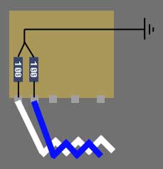
So what you are saying is remove the black wire that goes to the high voltage center tap to ground from the filament side of the PT, and hook both terminals of the filament OT lugs to their own 100 ohm resistor, short the other sides together and connect that to ground?
This is how it is now:
[img:240:180]http://farm3.static.flickr.com/2520/423 ... 2938_m.jpg[/img]
Is this what you mean?
[img:229:238]http://espen.sandelarsen.com/gallery/schematic.jpg[/img]
Docz
This is how it is now:
[img:240:180]http://farm3.static.flickr.com/2520/423 ... 2938_m.jpg[/img]
Is this what you mean?
[img:229:238]http://espen.sandelarsen.com/gallery/schematic.jpg[/img]
Docz
Re: Help! I tried to recap my amp!
Not exactly.
This has nothing to do with the high voltage winding.
We are talking about the 6.3 vac heater winding.
What is that black wire coming off the blue heater wire?
It looks like it is going over to the HV taps.
That would be a big NO!
Is that the center tap of the high voltage winding?
Sometimes we can get rid of most of the hum if we use a balanced center tap of the heater winding.
By using two 100 ohm resistors that you have verified are indeed 100 ohms, will most likely be a better center tap then the transformer.
Because when they wind those taps one side is always a bit more or less in the middle.
So by using the resistors you are making it much more balanced than it would be with the actual center tap of the winding.
Fender used to use a hum balance pot for this exact reason, to balance the voltage between the two heater wires.
So if you want to try it, your second drawing would be the way.
Just be sure if there is a heater center tap that you disconnect that wire and heat shrink the end of it or tape it off and snug it out of the way.
Tom
Don't let that smoke out!
Don't let that smoke out!
Re: Help! I tried to recap my amp!
Yes. Your drawing shows what to do. Make sure the ground side of the resistors is insulated from making unwanted contact. Stand them up, bend them towards the rear of the chassis (away from the PT) and run the ground to one of the transformer bolts. This is not part of the amplifier circuit ground. Any convenient spot on the chassis will do. Put a ring lug over the bolt, solder to it, and then add a second bolt. It looks like you have enough thread on the PT bolt to do that.docz wrote:So what you are saying is remove the black wire that goes to the high voltage center tap to ground from the filament side of the PT, and hook both terminals of the filament OT lugs to their own 100 ohm resistor, short the other sides together and connect that to ground?
Docz
Tom, too much in this tread to read back. I think you are on the wrong track. This is an odd ball situation. I think you are confusing the OP. See below.Structo wrote:Not exactly.
It seems to be a very badly done ground reference for the heaters. Imagine, using the HV CT to reference one side of the winding!!!What is that black wire coming off the blue heater wire?
It looks like it is going over to the HV taps.
Re: Help! I tried to recap my amp!
Ah, ok I think I get it now, so instead of using the center tap of the HV for ground reference, I will create a "center tap" on the 6.3V transformer, the resistors work by offering the same amount of resistance on both sides, and this simulates the resistance of the transformer coil correct?
DocZ
DocZ

Re: Help! I tried to recap my amp!
Hi Doc... your drawing is correct....
the whole idea is to balance the filament voltage around a ground reference. As it were, there was no way of balancing out the heater voltage. I've never seen a filament grounded one side... but then I can't claim to have "seen it all" related to tube amps.
Hope this can solve your hum problem.....
the whole idea is to balance the filament voltage around a ground reference. As it were, there was no way of balancing out the heater voltage. I've never seen a filament grounded one side... but then I can't claim to have "seen it all" related to tube amps.
Hope this can solve your hum problem.....
Re: Help! I tried to recap my amp!
Sorry I didn't mean to confuse you.
I will refrain from advising, it is making this overly complex when you have several people telling you what to do.
I will refrain from advising, it is making this overly complex when you have several people telling you what to do.
Tom
Don't let that smoke out!
Don't let that smoke out!
Re: Help! I tried to recap my amp!
I vote no to that idea.Structo wrote:I will refrain from advising
OP
The added noise is because someone changed the power tubes to El84's at sometime in the past???
I need an update on this post. I'm lost now.