5f1 first build

General discussion area for tube amps.

Moderators: pompeiisneaks, Colossal

Mikante
Posts: 214
Joined: Fri Oct 29, 2021 7:07 pm
Location: Italy

5f1 first build

Post by Mikante »

Hello, i am about to build my very first tub amp and it is going to be a 5f1 tweed champ, like for most of us.
I am collecting parts and schematics and ideas, i d like to keep it close to the original with just a few modification.
It is going to be a solid state rectifier and this is the only real difference.
I have few parts from a fender champion 600 but this is not mandatory.
I d like to use the same power transformer, it looks like it could be right for the job, specs are:
cp 600 230v
Ip 230v 50hz
Op 275v 6.3v
If i use this one i need to stick to ss rectifier.
Or i can purchase this one:
3C139DDF-7B00-4D53-A856-D4E82A0F17C6.jpeg
Power: 88VA
Input: 220-230-240V
Output:
- 270-0-270V - 0.12A
- 6.3V C.T. - 2A
- 5V - 2A
But i d like to keep it ss rectified. Is there a schematic for a 5f1 champ without the usual tube rectifier?

The output transformer is also not yet decided.
I could use the champion 600 one but it is to small and not very good in terms of quality. I can always replace it later.
I will only but a bypass switch on the negative feedback and apart form this, not other changes will be made.

Cabinet will be solid pine and custom made by me, i m a woodworker so no problems there 8)
Speaker will be a 4ohm, 10 inches, it s a warehouse veterans, which i already have and it is waiting for a small tube amp to fit in.
I have the chassis and and i have no problem working on metal too.

Any help will be very appreciated.
I m just starting with this project.
You do not have the required permissions to view the files attached to this post.
Stevem
Posts: 5144
Joined: Fri Jan 24, 2014 3:01 pm
Location: 1/3rd the way out one of the arms of the Milkyway.

Re: 5f1 first build

Post by Stevem »

Not using a tube recto is fine in a class A amp since it uses the most current at idle and has little sag to speak of, the important thing is that the B+ you end up with is within the range of running / keeping the output tube biased in class A.

Using a PT with about 30 volts more then you need will allow another filter node and dropping resistor before the output transformer and get rid of the idle hum these small class A amps always have.

For less noise hash in the audio stream I would use fast recovery type diodes, or if you have the recto’s already you want to use then add a.001 uf 600 volt ciramic disc cap across each diode.

For a output transformer I would really consider the one for champs that Mojotone sells.
It has both a 4 and 8 ohm winding and will open the door to a bunch more speakers you can try.

I have one in my Vibrochamp and use a Jensen 8 ohm driver.

I would use a 7 watt output tube cathode bypass resistor if your build calls for the common 5 watt type, and be sure to keep the cathode bypass cap well away from the heat of that resistor or any others that are more then 1 watt types.
When I die, I want to go like my Grandfather did, peacefully in his sleep.
Not screaming like the passengers in his car!

Cutting out a man's tongue does not mean he’s a liar, but it does show that you fear the truth he might speak about you!
Mikante
Posts: 214
Joined: Fri Oct 29, 2021 7:07 pm
Location: Italy

Re: 5f1 first build

Post by Mikante »

Hello,
The power transformer was recommended by the tech support. The one i listed from Piemme Elektra, it an italian brand.
The secondary is 270 0 270 and it looks like it is within the range, i m saying this by looking at other pt from well known brands.
Still trying to learn.

Also about the rectifier, i know nothing, about b+, same.
That is why i asked the tech support.
I m searhing for a 5f1 schematic with a solid state rectifier but had no luck finding one.
This would help me because i still need to learn a lot.
I m not in a hurry.
User avatar
johnnyreece
Posts: 1072
Joined: Thu Jan 26, 2012 2:05 am
Location: New Castle, IN

Re: 5f1 first build

Post by johnnyreece »

A 250-0-250V transformer would get you more in line with what the original voltages, if using SS rectification.
Mikante
Posts: 214
Joined: Fri Oct 29, 2021 7:07 pm
Location: Italy

Re: 5f1 first build

Post by Mikante »

I m really still up for anything, i d like the SS rectifier also because I thought it could be easier to build, i guess it is quite the opposite especially when there are no schematics to follow.
I wanted to save some money and use the old transformer from the champion 600, that is another reason why.
Anyway i have found this
image-2610034339.jpg
And reading on another forum that it is very simple to add a solid rectifier to the 5f1 champ.
This guy is only wiring 4 1n4007 diodes directly on the 5y3 pins.
The ss rectifier on my 600 champ looks much more complicated, not only diodes but also 6 capacitors, 4 ceramic and other two.
Here a picture
8C6D43DE-E3BA-4897-9729-890D703C4E11.jpeg
Anyway when i asked the tech support for the transformer i forgot to say that i wanted ss rectifier. Maybe they have a 250 0 250 available to.
You do not have the required permissions to view the files attached to this post.
Last edited by Mikante on Wed Jun 15, 2022 6:39 pm, edited 3 times in total.
User avatar
johnnyreece
Posts: 1072
Joined: Thu Jan 26, 2012 2:05 am
Location: New Castle, IN

Re: 5f1 first build

Post by johnnyreece »

Correct. Depending on the current draw, a 5y3 rectifier will drop somewhere around 60 volts, and you'll only get around 1.1 times the voltage to the plates, where a SS diode will only drop one volt, and you get around 1.41 times the voltage.
Stevem
Posts: 5144
Joined: Fri Jan 24, 2014 3:01 pm
Location: 1/3rd the way out one of the arms of the Milkyway.

Re: 5f1 first build

Post by Stevem »

Those 4 blue caps are the .001 Uf snubber caps I posted about.
When I die, I want to go like my Grandfather did, peacefully in his sleep.
Not screaming like the passengers in his car!

Cutting out a man's tongue does not mean he’s a liar, but it does show that you fear the truth he might speak about you!
Mikante
Posts: 214
Joined: Fri Oct 29, 2021 7:07 pm
Location: Italy

Re: 5f1 first build

Post by Mikante »

Yes and now I understand what you meant. What are the others two about?
Screenshot_20220615-223229_Samsung Notes.jpg
You do not have the required permissions to view the files attached to this post.
User avatar
statorvane
Posts: 568
Joined: Thu May 11, 2006 3:28 pm
Location: Upstate New York

Re: 5f1 first build

Post by statorvane »

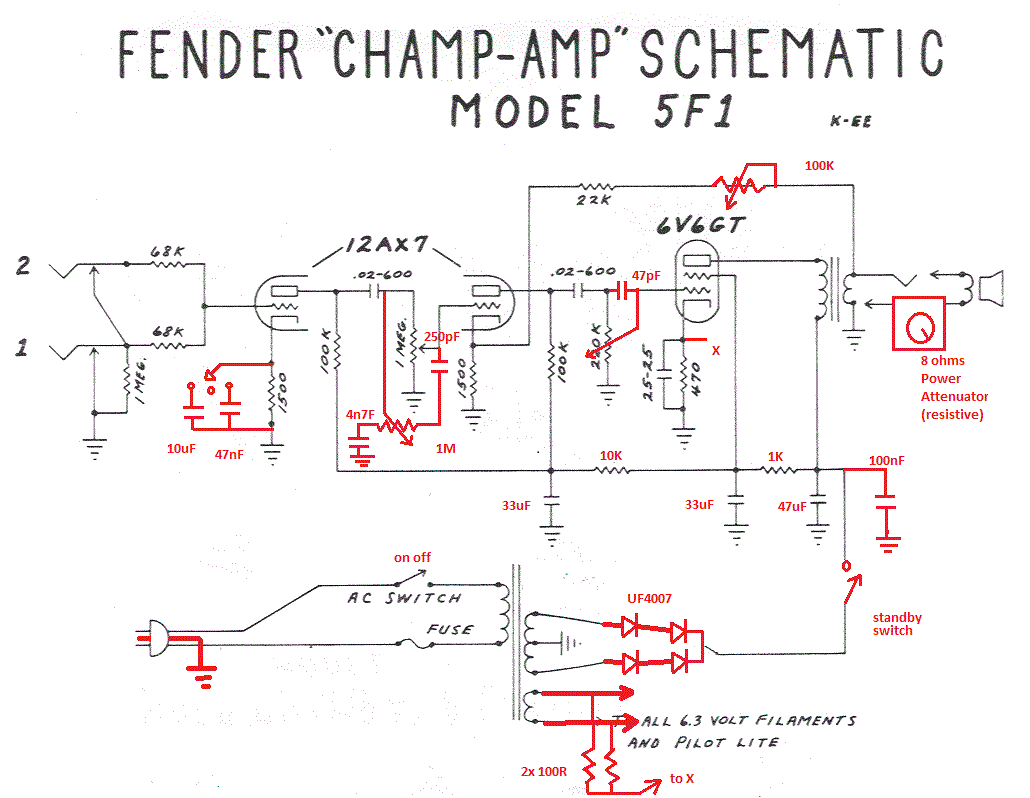
I found a champ schematic with a solid state rectifier (below). This rectifier uses ultrafast swtiching diodes, so you can dispense with the snubber capacitors.

I would ignore the rest of the modifications shown on the schematic. This will get you going replacing the tube rectifier. If interested, you can investigate the other modifications once you have built the amp .

Image
Mikante
Posts: 214
Joined: Fri Oct 29, 2021 7:07 pm
Location: Italy

Re: 5f1 first build

Post by Mikante »

This is what i was looking for, thank you very much.
I also found more interesting infos.
6C715F65-FBD6-4E4F-8014-618927430AAB.png
I could use a Zener 5 watt diode to drop the voltage a little bit. I could then use the pt from the champion 600 and save a lot of money.
I guess this is why i found so many threads about the fender 600 running too hot or with a fried screen grid resistor?
My stopped working too, r11 is burned on one side but the value still measures the same. The filter capacitor next to this resistor shows values completely off. I have no way of checking the 6v6 but it looks perfect.
Anyway, as i said, i could try using the same power transformer dropping the secondary down with a zener diode and use the money to buy a good Ot.
You do not have the required permissions to view the files attached to this post.
User avatar
martin manning
Posts: 14308
Joined: Sun Jul 06, 2008 12:43 am
Location: 39°06' N 84°30' W

Re: 5f1 first build

Post by martin manning »

I would rather add another RC filter and use that to drop excess voltage and reduce hum as suggested by Steve.
ChopSauce
Posts: 1045
Joined: Wed Mar 15, 2017 12:08 pm
Location: So Paris, France

Re: 5f1 first build

Post by ChopSauce »

Just out of curiosity: why don't you simply manage to mod the Champ 600 (that is rebuild the circuit on an eyelet board for example) as close as possible to a 5F1?

If you don't have neither the vintage transformer, nor the vintage speaker, your amp is not going to sound exactly like an original anyway, so why bother?

I'd start examining the schematic for both & then sketch what I think would be a proper mix. If you do this, post it here and I'm sure there will be someone to help you with designing something that works.

I wouldn't bother with the size of the Champ output transformer, either, for the original 5F1 OT is not something big at all, either. Nor would I change the PT, as there are several ways to manage with the voltages, as suggested earlier.

Great projet and good opportunity to learn some more about building tube amps at lowest cost, by the way ... 8)
Mikante
Posts: 214
Joined: Fri Oct 29, 2021 7:07 pm
Location: Italy

Re: 5f1 first build

Post by Mikante »

Hello, as i said, nothing is yet decided.
Replacing the pcb board with a point to point circuit was my first choice.
First, it would be easy for me to follow the pcb i already have, second, it would be cheaper.
I dont know about the original 5c1 champion, the reissue is very different and closer ti the 5f1, it sounded great with the tone stack out of the way. But at one point it failed and stopped working. I have investigated and found a bunch of threads about the same exact problem.
This circuit along with its parts is running way to hot and very often fails in the same why. R10 which is the screen grid resistor dies and the 6v6 goes along. It might be because of the cheap parts and filter caps and tubes but i had a decent electro harmonix in the power tube socket and my champ failed in the same way.
I m learning a lot right now and putting all the infos i collected together i can say that the power transformer is giving to much volts.
This along with some arguable choice in the circuit design such as the power tube bias is causing the amp to be good sounding but unreliable.
I thought it could be easier to swap in a 5f1 board but i found my self to be incompetent to say at least. So I took the chance to talk with you and learn something through.
About the output transformer. I would not mind to have a better one. The stock is decent but not good. I was going to swap it for a better one anyway.

@Martin how would you add a rc filter?
ChopSauce
Posts: 1045
Joined: Wed Mar 15, 2017 12:08 pm
Location: So Paris, France

Re: 5f1 first build

Post by ChopSauce »

May http://www.valvewizard.co.uk/smoothing.html help?

& I repeat one last time - at least that worked for me : start sketching, by comparing the 5F1 circuit with the vintage Vox AC4 one, for example. If I'm not mistaking, the AC4 has that first filter "cell" that the 5F1 hasn't, which would help with slightly reducing the voltages.

The Dumble take over the Champ https://tubeamparchive.com/viewtopic.php?f=5&t=25599 also might be worth looking at.
Mikante
Posts: 214
Joined: Fri Oct 29, 2021 7:07 pm
Location: Italy

Re: 5f1 first build

Post by Mikante »

Hello,
I m already following your advice, it is simplier for me to upgrade the 600 champ to a point to point type of circuit, using both transformers, switch and lamp, along with the rectifier circuit.
8443EA5F-2921-4357-BCD5-9F5D3B6E5C29.png
I have just read the file about the “smoothing” that you provided with the link.
I m just a little confused now. In the the schematic above you can see there is a 0.1 250v cap on the primary and a 0.1 600v cap on the secondary right before the rectifier bridge and without a resistor in parallel, so i guess this was not meant for smoothing. Is this meant just as a voltage drop?
You do not have the required permissions to view the files attached to this post.
Post Reply