VALVE RECTIFIER "BACK UP DIODES"
Moderators: pompeiisneaks, Colossal
-
martin manning

- Posts: 14308
- Joined: Sun Jul 06, 2008 12:43 am
- Location: 39°06' N 84°30' W
1 others liked this
Re: VALVE RECTIFIER "BACK UP DIODES"
The other caution against a HT CT fuse is that if it opens, the bias supply tap becomes the new CT, and the bias supply caps are likely to be damaged.

Re: VALVE RECTIFIER "BACK UP DIODES"
I’m not using a standby switch. I’ve got the 3A slow fuse in the 120V AC mains and the pair of double 1N4007s on the rectifier plates. I’ve been trying to follow Blencoe’s advice on fuse placement in the AC line only, I just wondered if an HT secondary into a 500mA fast fuse into two 1N4007s in series into the tube rectifier plate was overkill?
Just plug it in, man.
Re: VALVE RECTIFIER "BACK UP DIODES"
I'ma bit confused, sorry, the fuse I suggested is on a secondary, the CT of the HT winding; if it blows, HT current will stop, but yes, the PT will still be energised, but that's the nature of fusing on the secondary.Colossal wrote: ↑Fri Mar 11, 2022 6:31 pmPete,pdf64 wrote: ↑Fri Mar 11, 2022 6:08 pm Given that with the the doubled up protection diodes, a short across the HT winding seems somewhat unlikely, so a single fuse between the winding CT and its return to 0V common may be reasonable.
If you get rid of standby, that fuse can be a fast acting type, and the fast acting fuse after the reservoir cap would be superfluous.
What troubles me with fusing a CT is that a PT can still remain energized after a fault. Is that not the case here? I would think fusing the secondaries would be preferable, or barring that, have a single B+ fuse downstream of the rectifier.
Thanks
Good point, but in this case the cap spec is for 150V, which should be ok; if the CT fuse blows, this type of bias supply usually tends to settle around -100V https://el34world.com/charts/Schematics ... _schem.pdfmartin manning wrote: ↑Fri Mar 11, 2022 6:37 pm The other caution against a HT CT fuse is that if it opens, the bias supply tap becomes the new CT, and the bias supply caps are likely to be damaged.
Bear in mind that eg a valve or bias supply fault might slowly cook the transformers, without ever blowing a 3A sloblo, until something actually shorted.ViperDoc wrote: ↑Fri Mar 11, 2022 6:39 pm I’m not using a standby switch. I’ve got the 3A slow fuse in the 120V AC mains and the pair of double 1N4007s on the rectifier plates. I’ve been trying to follow Blencoe’s advice on fuse placement in the AC line only, I just wondered if an HT secondary into a 500mA fast fuse into two 1N4007s in series into the tube rectifier plate was overkill?
A good thing with secondary fusing is that the likelihood of a fault causing collaterol damage may be reduced.
https://www.justgiving.com/page/5-in-5-for-charlie This is my step son and his family. He is running 5 marathons in 5 days to support the research into STXBP1, the genetic condition my grandson Charlie has. Please consider supporting him!
-
martin manning
- Posts: 14308
- Joined: Sun Jul 06, 2008 12:43 am
- Location: 39°06' N 84°30' W
1 others liked this
Re: VALVE RECTIFIER "BACK UP DIODES"
I think the first bias cap could see something close to B+ transiently.pdf64 wrote: ↑Fri Mar 11, 2022 7:08 pmGood point, but in this case the cap spec is for 150V, which should be ok; if the CT fuse blows, this type of bias supply usually tends to settle around -100V https://el34world.com/charts/Schematics ... _schem.pdfmartin manning wrote: ↑Fri Mar 11, 2022 6:37 pm The other caution against a HT CT fuse is that if it opens, the bias supply tap becomes the new CT, and the bias supply caps are likely to be damaged.
Re: VALVE RECTIFIER "BACK UP DIODES"
The topic of using fuses for protection is a long and winding road.
If you want to protect your power transformer, put a fuse in each half-secondary, not in the CT. An open CT can damage other stuff, as the previous notes point out. As an aside, the PT is often the single most expensive part in your amp. The input AC line fuse is NOT there to protect your PT. It's there to stop a shorted PT or other issues from starting a fire. Protecting a transformer means putting a fuse in each independent section of winding. CTs are not independent.t's
Rectifier tubes and output tubes may or may not be so expensive you need to protect them. Your call on this one. Your output transformer may be expensive enough. A properly sized fuse may protect your OT if it's after the filter caps. A properly sized fuse after the rectifiers and before the filter caps may protect your filter caps, possibly your OT.
The incoming AC line fuse will not necessarily protect your PT against a shorted heater winding. Been there, done the math. A heater short can burnout the heater winding or cook the HV secondary until it shorts without blowing the main AC fuse.
There is a tendency of people faced with this to say "Wait a minute. It's ridiculous to think of fusing everything all the time when [insert "my father's/grandfather's/old Fenders/etc.] amps never had that and they did all right!" Yes, that is true. Doing protection of anything electronic requires clear-eyed and sober consideration of what is to be protected, how likely a failure or chain-failure is, and whether you want to spend the money and time on insurance to prevent the consequent damage instead of just repairing it.
"It's not what we don't know that gets us in trouble. It's what we know for sure that just ain't so"
Mark Twain
Mark Twain
Re: VALVE RECTIFIER "BACK UP DIODES"
Such great info, guys. OK, I'll fuse the secondary. I usually do this anyway, but I decided to work in the tweed chassis and real estate is NOT abundant. But I've got a plan. Thanks again!
Just plug it in, man.

Re: VALVE RECTIFIER "BACK UP DIODES"
You can buy leaded 5x20mm style fuses than can make it a lot easier to retrofit than having to insert fuse holders.
Protection is many facetted. Although the 3A mains side fuse is default value, you may be able to reduce that via careful consideration. Such as measuring the continuous/cranked mains rms current, and adding some margin for the various types of energisation peak requirements. Fuses take time to work, dependant on the level of fault over-current that can occur, and there can be quite a practical reduction in blow time for a 2A fuse versus a 3A fuse, and that can reduce stress on parts.
As indicated, the typical method of secondary side protection where there is a bias supply is to fuse each secondary winding arm (ie. not the CT). You could guess the value of the fuse to use, or see what others have used and that has not blown intermittently (ie. marginal fuse value). You could try and technically design the fuse value based on that amps specific power supply - that can take some effort on your part as it involves measuring PT winding resistances and cranked DC load current - that can be done on this thread and the background of that is in the https://www.dalmura.com.au/static/Valve ... fusing.pdf - and it is worth aiming to use the lowest practical fuse value for the same reason as lowering the primary side fuse value. Imho fusing the secondary winding is the safest and first line of protection appropriate for the secondary side circuitry, as the fuse 'operates' on AC current (which is what the fuse is designed to do) and covers most of the fault conditions. I don't subscribe to fusing the B+ path in general for many reasons.
You may want to consider the next practical fault conditions related to the quad output stage valves. There are a few 'common' faults that can occur and it can be worthwhile appreciating what if anything can be done to mitigate each common fault and whether it is worth making a subtle change to include better protection. You can google search around how others have added extra protection, and I have some thoughts on that topic in https://www.dalmura.com.au/static/Outpu ... ection.pdf.
Ciao, Tim
Re: VALVE RECTIFIER "BACK UP DIODES"
When it rains, it pours. This is great information. Thank you.
Here's a schematic of my 5F8A power supply, designed with a bevy of help from Colossal, and including the dual HT fuses and backup diodes as discussed.
I was in the process of making a bias board when this discussion flourished, and I was able to modify it per the discussion. You all do this so much better than me, but here's where it's at presently. I left the top turrets open to allow for a bias voltage dropping resistor as needed, and that will determine where I put my bias diode. The bias grounds to a ground tab secured to chassis by the bias board standoff and bolt. The left chassis/cabinet-mounting bolt will need to get a haircut to fit, but I'll make it work. I did consider adapting a capture nut, but we'll see what seems reasonable.
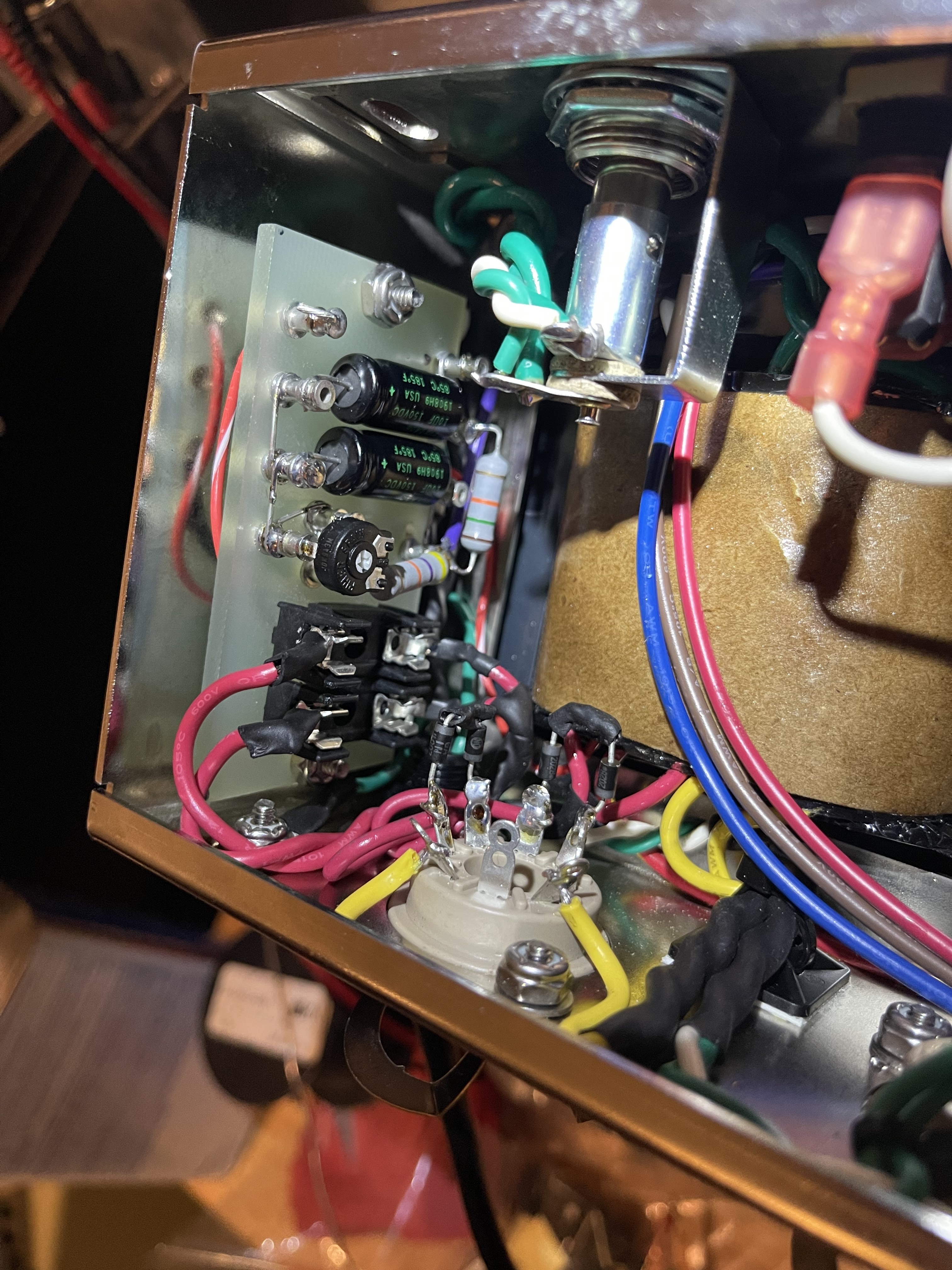
You do not have the required permissions to view the files attached to this post.
Just plug it in, man.