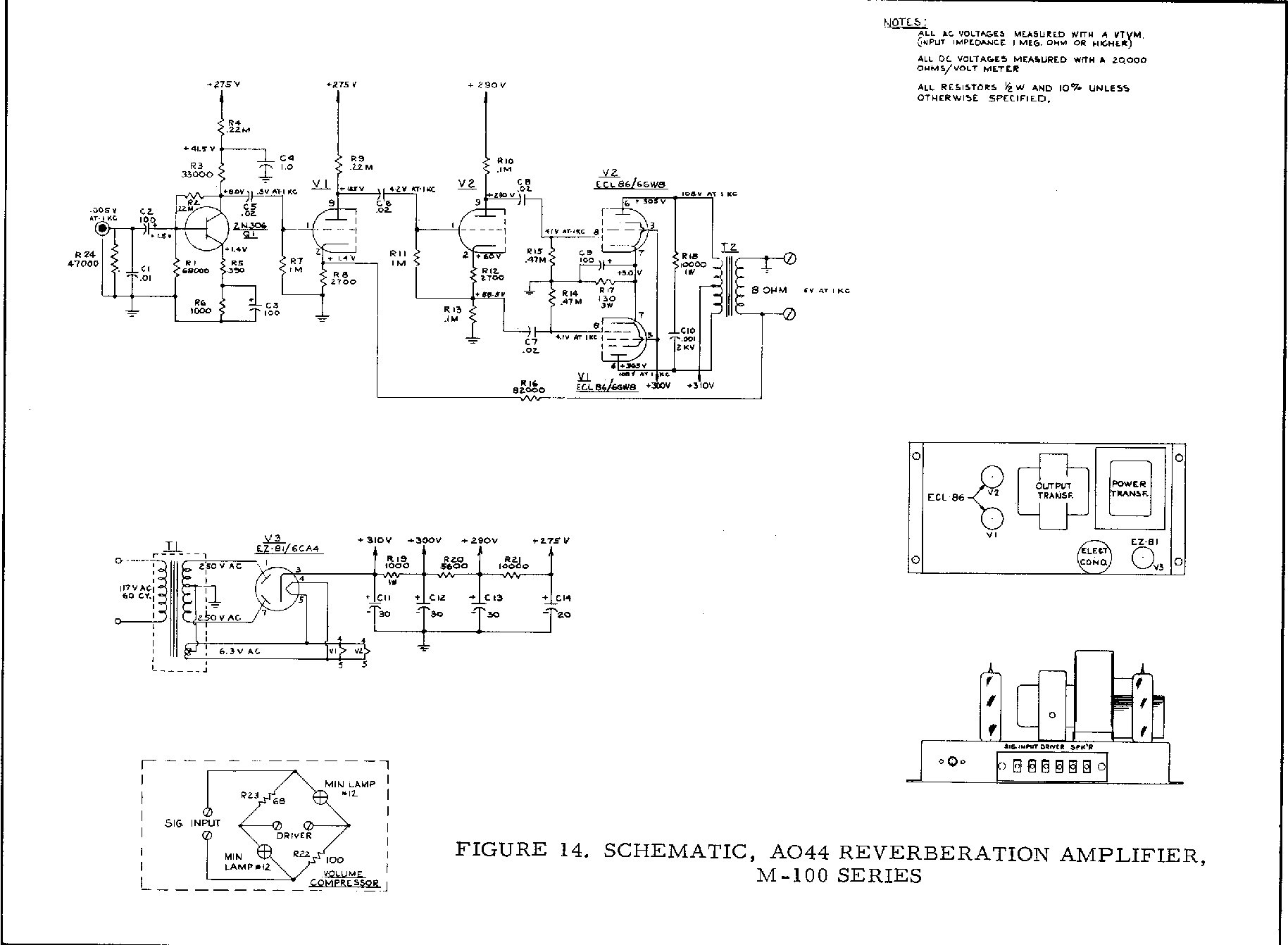
This must have been right there at the beginning of the end. Check out the bias arrangement on the transistor. It's a tube!! ECl-86 final.
Anyway, I found it interesting.
http://www.captain-foldback.com/Hammond ... s/AO44.jpg
Check this out
Moderators: pompeiisneaks, Colossal
-
skyboltone

- Posts: 2287
- Joined: Wed May 10, 2006 7:02 pm
- Location: Sparks, NV, where nowhere looks like home.
Check this out
The Last of the World's Great Human Beings
Seek immediate medical attention if you suddenly go either deaf or blind.
If you put the Federal Government in charge of the Sahara Desert, in five years time there would be a shortage of sand.
Seek immediate medical attention if you suddenly go either deaf or blind.
If you put the Federal Government in charge of the Sahara Desert, in five years time there would be a shortage of sand.

Re: Check this out
> Check out the bias arrangement on the transistor. It's a tube!!
??? It's a transistor working from a tube power supply.
Come down R4. It derives a 41V supply which a transistor can eat.
The base is 0.1V positive of the emitter. That's quite unlikely for a small-signal vacuum tube, but about right for a transistor. You may be thinking "0.7V!", but that's Silicon. This is probably Germanium which has half the Shockley's Law voltage. Also high C-B leakage current. Also don't take the base voltage too literally since it is a high-impednace point and meter-loading drops the observed voltage.
If the input sensitivity is near 0.004V as shown, noise is an issue and transistor may be a better bet than a tube. Microphonics tend to be lower (not zero on the old grease-filled cans). Later really-clean transistors, at these values, could get noise voltage near that 350 resistor or say 0.4uV, compared with 2uV-5uV for selected tubes at similar current. The oldest Ge BJTs hissed like a snake, but by ~1960 they were displacing tubes in low voltage noise applications (and we discovered current noise).
Input impedance may be near 4K ohms. That comes from Miller effect of gain of 0.3V/0.005V= 60 across R2 220K. 220K/60= 4.6K, and R24 R1. Also the 0.01uFd cap suggests a source impedance not more than a couple K ohms.
Ah! Duh! This comes right off the reverb tank. Which is wound to a slightly lower Z than we use with a 12AX7 recovery amp. The input cap is customary to take some of the tizzz off the spring and pickup. And then the diamond bridge lower-left goes between the Main speaker output and the reverb tank input. The lamps reduce the risk of burning up the tank driver coil, and the nasty sounds when the main channel drives the reverb channel too hard.
This type reverb, non-adjustable, is always a problem because it hisses in the quiet parts. You fix that with big drive and less recovery gain, but then it burns out on heavy drive. And these were eXpen$ive accessories on eXpen$ive systems, so the cost of bleeding-edge devices and sorting to find a good one was not a big deal.