This schematic is near complete. Can someone look over the B+ rail and tell me uf i did anything wrong? I need to be sure B+1 ~ B+5 are correct. I think im missing a resistor or something.
-------------------------------------------------------------------------------
Ok im moved the choke before the two 9.1k resistors and i changed the wiper on the cut potentiometer and made v4 tail resistor 2.2K.
I do not see v2a pin 3 being a problem. Looking at the rocketreverblayout it shows it as 2.2K|22uF/50v to ground.
Now the last few things i do not understand from the rocketreverbfinal layout is that power supply board with has 2 resistors that seem to be under the board. What are those resistors? And also what wattage should the power, grid, screen and PI tail resistors be?
Thanks everyone!
Rocket w/ Reverb
Moderators: pompeiisneaks, Colossal
Re: Rocket w/ Reverb
Last edited by ampbldr2 on Fri Mar 25, 2011 3:52 pm, edited 2 times in total.
Re: Rocket w/ Reverb
I think this is near complete so if anyone can find any mistakes let me know.ampbldr2 wrote:This schematic is near complete. Can someone look over the B+ rail and tell me uf i did anything wrong? I need to be sure B+1 ~ B+5 are correct. I think im missing a resistor or something.

Re: Rocket w/ Reverb
The choke needs to be move back infront of the two 9k1 resistors.
You do not have the required permissions to view the files attached to this post.
Re: Rocket w/ Reverb
Pic attached, easier than words. Also you have a 1K tail resistor at V4a/b vs 1K2, and 68K vs 56K on V2a. Nearly there. Cut pot wiper is not connected. That's about it I think...I can see you are one of those peeps who wants EVERYTHING on one page  It's a good idea.
You do not have the required permissions to view the files attached to this post.
Re: Rocket w/ Reverb
ampbldr2 wrote:This schematic is near complete. Can someone look over the B+ rail and tell me uf i did anything wrong? I need to be sure B+1 ~ B+5 are correct. I think im missing a resistor or something.
-------------------------------------------------------------------------------
Ok im moved the choke before the two 9.1k resistors and i changed the wiper on the cut potentiometer and made v4 tail resistor 2.2K.
I do not see v2a pin 3 being a problem. Looking at the rocketreverblayout it shows it as 2.2K|22uF/50v to ground.
Now the last few things i do not understand from the rocketreverbfinal layout is that power supply board with has 2 resistors that seem to be under the board. What are those resistors? And also what wattage should the power, grid, screen and PI tail resistors be?
Thanks everyone!
I made the changes based on Mark and Ian comments. Can you take another look?
Re: Rocket w/ Reverb
Ok this is about as close as it gets. Sorry for all the edits here but i think this is correct. I really have a hard time following the layout that normster did. What are those resistors on the bottom side of the power supply board?ampbldr2 wrote:ampbldr2 wrote:This schematic is near complete. Can someone look over the B+ rail and tell me uf i did anything wrong? I need to be sure B+1 ~ B+5 are correct. I think im missing a resistor or something.
-------------------------------------------------------------------------------
Ok im moved the choke before the two 9.1k resistors and i changed the wiper on the cut potentiometer and made v4 tail resistor 2.2K.
I do not see v2a pin 3 being a problem. Looking at the rocketreverblayout it shows it as 2.2K|22uF/50v to ground.
Now the last few things i do not understand from the rocketreverbfinal layout is that power supply board with has 2 resistors that seem to be under the board. What are those resistors? And also what wattage should the power, grid, screen and PI tail resistors be?
Thanks everyone!
I made the changes based on Mark and Ian comments. Can you take another look?
Last edited by ampbldr2 on Mon Mar 28, 2011 2:12 pm, edited 1 time in total.

Bright cap
I think you will find that the 500pf is over the top on this amp. 120pf and half that are useable IMHO. Boost avail at foot-pedal is a nice tool.
Ange
Ange
-
statorvane

- Posts: 568
- Joined: Thu May 11, 2006 3:28 pm
- Location: Upstate New York
Re: Rocket w/ Reverb
That is a fine schematic. I know how long it takes to do this kind of work.
Only thing I noticed, and I did not see anyone else point this out, if V9 is a GZ34 (or 5AR4) - that is a 5V rectifier, but V9 is shown hooked up to the 6.3V filament supply.
Again, I think that is a really good effort there.
Only thing I noticed, and I did not see anyone else point this out, if V9 is a GZ34 (or 5AR4) - that is a 5V rectifier, but V9 is shown hooked up to the 6.3V filament supply.
Again, I think that is a really good effort there.
-
RJ Guitars

- Posts: 2663
- Joined: Tue Nov 14, 2006 3:49 am
- Location: Los Alamos, New Mexico
- Contact:
Re: Rocket w/ Reverb
Take a look at your transformer labels - the power tranny should be the HTS-9144 and the output the HTS-8093-1. I suspect you knew that but the labels appear to be reversed.
Good, Fast, or Cheap -- Pick two...
http://www.rjguitars.net
http://www.rjaudioresearch.com/
http://diyguitaramps.prophpbb.com/
http://www.rjguitars.net
http://www.rjaudioresearch.com/
http://diyguitaramps.prophpbb.com/
Re: Rocket w/ Reverb
The power supply filtering is still incorrect. T2>C22>R37 R38>C20>R24>C6>R5>C4.
Have a read of this, it might help with understanding the filters in power supplies.
http://valvewizard1.webs.com/smoothing.html
Have a read of this, it might help with understanding the filters in power supplies.
http://valvewizard1.webs.com/smoothing.html
Re: Rocket w/ Reverb
Ian444 wrote:The power supply filtering is still incorrect. T2>C22>R37 R38>C20>R24>C6>R5>C4.
Have a read of this, it might help with understanding the filters in power supplies.
http://valvewizard1.webs.com/smoothing.html
I have the power suppy rail corrected now in this schematic v1.5. I also corrected the 5VAC connection to the recitifier and added the 100ohm resistors to lift the heaters. Changed R17 and R21 to 1watt resistors.
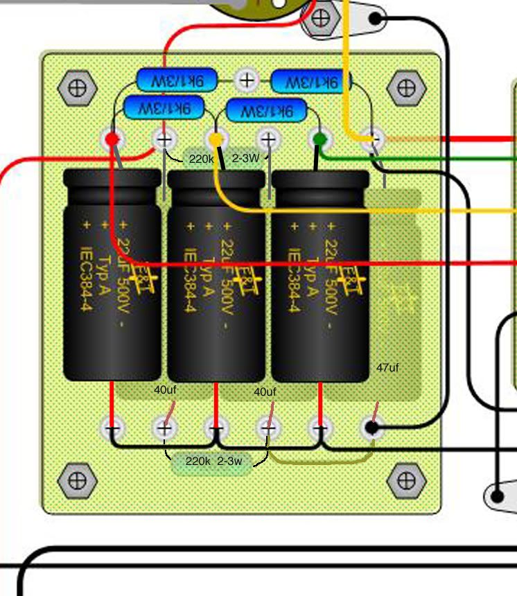
I still did not have any response to what those 2 resistors are on the bottom side of the power supply board on the normster layout. One looks like a 223K and the other I have no clue. Any ideas or am in missing somethng.
You do not have the required permissions to view the files attached to this post.
Last edited by ampbldr2 on Mon Mar 28, 2011 6:49 pm, edited 1 time in total.
reply
I was wondering about that as well and did some digging, I cannot remember if this was info from Norm. I would verify this. I am pretty sure that they serve as 'drain' caps.
[IMG:746:860]http://i260.photobucket.com/albums/ii9/ ... -power.jpg[/img]
[IMG:746:860]http://i260.photobucket.com/albums/ii9/ ... -power.jpg[/img]
Re: reply
Interesting to see there are a mix of supply caps too. 1-47uF 2-40uF and 3-20uF caps. Maybe others can chime in how this is supposed to be wired.angelodp wrote:I was wondering about that as well and did some digging, I cannot remember if this was info from Norm. I would verify this. I am pretty sure that they serve as 'drain' caps.
[IMG:746:860]http://i260.photobucket.com/albums/ii9/ ... -power.jpg[/img]
-
RJ Guitars
- Posts: 2663
- Joined: Tue Nov 14, 2006 3:49 am
- Location: Los Alamos, New Mexico
- Contact:
Re: reply
FWIW - my 2 cents - The pair of 40uF's are paralleled so they make 80uF. That is the Trainwreck standard and it looks like they wanted to preserve that. You could also accomplish that using a 47uF and a 33uF and achieve a similar result. The 47uF in the picture is "close enough" to the 40uF that Trainwreck typically uses and allows you to use a modern production cap in that spot. There are three 22uF caps on that board which are again "close enough" to the Trainwreck specification 20uF and allow you to use modern production values there as well.ampbldr2 wrote:... Interesting to see there are a mix of supply caps too. 1-47uF 2-40uF and 3-20uF caps. Maybe others can chime in how this is supposed to be wired.
rj
Good, Fast, or Cheap -- Pick two...
http://www.rjguitars.net
http://www.rjaudioresearch.com/
http://diyguitaramps.prophpbb.com/
http://www.rjguitars.net
http://www.rjaudioresearch.com/
http://diyguitaramps.prophpbb.com/
Re: Rocket w/ Reverb
Those 220k resistors are balance resistors for the two 40uf caps on the bottom, not bleeder resistors.
Mark
Mark