Adding a VVR won't be easy. Here's a pic of the innards:
[img

768]
http://i590.photobucket.com/albums/ss34 ... x_nt_1.jpg[/img]
From blinker_2009's album on Photobucket.
Where will you locate the VVR? Hint: leads to the mosfet should be as short as possible and the VVR should be located in a "quiet" section of the amp.

When you'll have found a suitable location, modding will be quite easy. The NT uses a peculiar post-PI structure, with a 100n cap in series, a 470K grid leak R to ground, another 100n cap in series, the MV and a 3K3 grid stop to the EL84.
You may jumper the PCB from the top of the 470K straight to the grid stop or after the second 100n to the grid stop.
A cleaner mod would be to jumper the PCB from the grid leak R, use a 47n (or 22n cap) and a 8K2 stop in order to somewhat defart the amp. While the iron is still hot, I'd also change the screen Rs (470R/1W) for 1K or 1K5 / 3W models. You'll better protect the EL84s if you play really loud and sound will be overall smoother.
Any mods should be done very carefully: too much heat and you'll lift or destroy PCB traces.

 768]
768]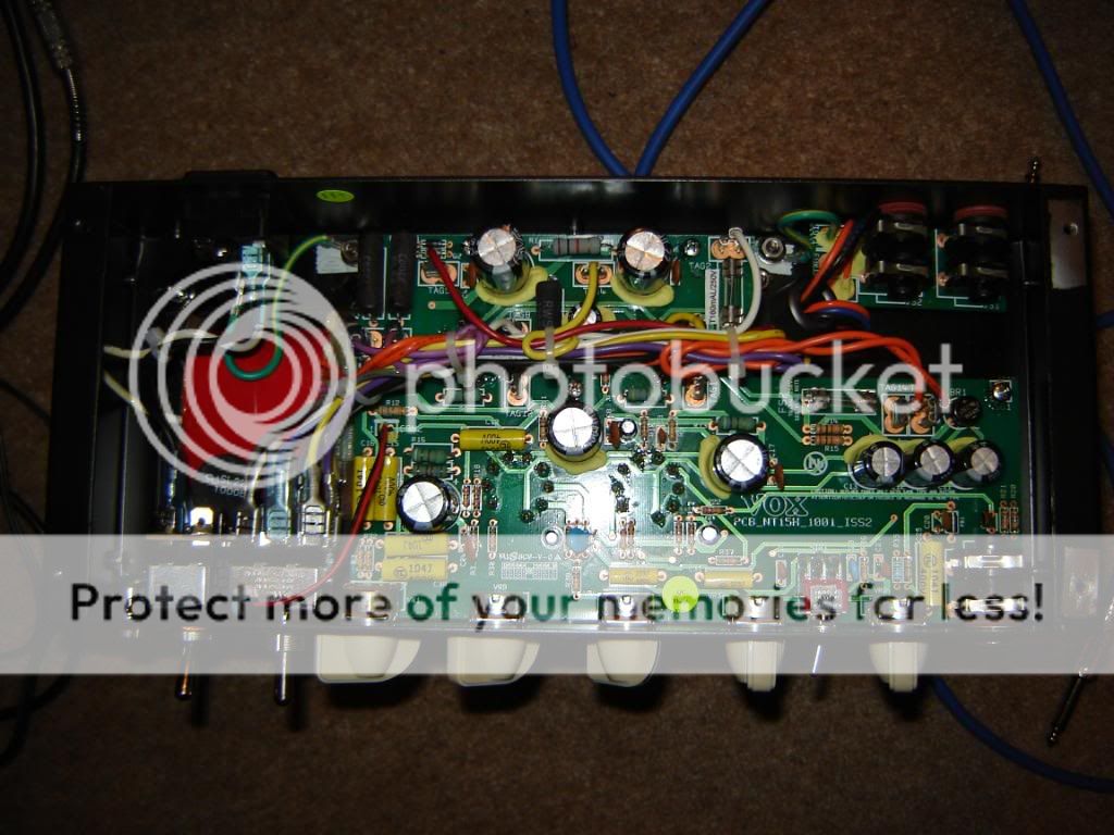