This is what I was trying to ask. Is this correct? Wierd thing is that I couldnt find the under board wire...
[IMG:799:449]http://img.photobucket.com/albums/v299/ ... 00_270.jpg[/img]
Nothings soldered or anything.
Help sorting out whats going on with heavily modded bassman
Moderators: pompeiisneaks, Colossal
Re: Help sorting out whats going on with heavily modded bassman
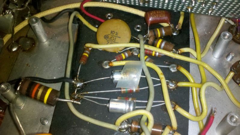
In the AA864, the feedback resistor would go from the empty eyelet next to the .1 cap, up to the eyelet where you have the feedback wire now. One end of the .1 and the 22K tail resistor would go there, too. Then your 100R goes straight across to the ground. Close to the same (electrically) as what you have done. I can't read the feedback resistor: 820R? The shunt resistor looks like 120R; out of 100s?
As to the underboard wire, it looks like it has been replaced with the yellow wire going to the top of the coupling cap. You have bare jumper wire from there up to the 120R. Get that out of there or the amp will not work.
As to the underboard wire, it looks like it has been replaced with the yellow wire going to the top of the coupling cap. You have bare jumper wire from there up to the 120R. Get that out of there or the amp will not work.
Re: Help sorting out whats going on with heavily modded bassman
Sorry had to step out to my sons ball game. How about this now short of those 220ks that would be on the two empty eyelets it looks just like it does on the layout Is this correct. The yellow wire on top of the 500pf goes to v3's plate.Firestorm wrote:In the AA864, the feedback resistor would go from the empty eyelet next to the .1 cap, up to the eyelet where you have the feedback wire now. One end of the .1 and the 22K tail resistor would go there, too. Then your 100R goes straight across to the ground. Close to the same (electrically) as what you have done. I can't read the feedback resistor: 820R? The shunt resistor looks like 120R; out of 100s?
As to the underboard wire, it looks like it has been replaced with the yellow wire going to the top of the coupling cap. You have bare jumper wire from there up to the 120R. Get that out of there or the amp will not work.
resistor from pin 6.
[IMG:799:449]http://img.photobucket.com/albums/v299/ ... 07_420.jpg[/img]
John
Re: Help sorting out whats going on with heavily modded bassman
Yes the feedback resistor is 820 ohms. Whats the shunt resistor? If thats the one going to the cathode resistor ground then its a 100 ohm.john l wrote:Sorry had to step out to my sons ball game. How about this now short of those 220ks that would be on the two empty eyelets it looks just like it does on the layout Is this correct. The yellow wire on top of the 500pf goes to v3's plate.Firestorm wrote:In the AA864, the feedback resistor would go from the empty eyelet next to the .1 cap, up to the eyelet where you have the feedback wire now. One end of the .1 and the 22K tail resistor would go there, too. Then your 100R goes straight across to the ground. Close to the same (electrically) as what you have done. I can't read the feedback resistor: 820R? The shunt resistor looks like 120R; out of 100s?
As to the underboard wire, it looks like it has been replaced with the yellow wire going to the top of the coupling cap. You have bare jumper wire from there up to the 120R. Get that out of there or the amp will not work.
resistor from pin 6.
[IMG:799:449]http://img.photobucket.com/albums/v299/ ... 07_420.jpg[/img]
John
Re: Help sorting out whats going on with heavily modded bassman
Looks right. On my screen, the middle band of your 100R looks red, so I thought it was 120. Not too much difference anyway.
Remember to flip the phase of the OT Also: there's a yellow wire at the top of the pic coming from the ground where the 100R will get soldered. Where does that go? I don't think that should be there; looks like a leftover.
Remember to flip the phase of the OT Also: there's a yellow wire at the top of the pic coming from the ground where the 100R will get soldered. Where does that go? I don't think that should be there; looks like a leftover.
Last edited by Firestorm on Sat Mar 17, 2012 3:46 pm, edited 1 time in total.
Re: Help sorting out whats going on with heavily modded bassman
Yeah the yellow wires gone, thats how the old assembly grounded there. Check out the pics on the first page of the thread and youll see it. Your absolutey right about the resistor being a 120R Ill have to change it out! Good catch.Firestorm wrote:Looks right. On my screen, the middle band of your 100R looks red, so I thought it was 120. Not too much difference anyway.
Remember to flip the phase of the OAlso: there's a yellow wire at the top of the pic coming from the ground where the 100R will get soldered. Where does that go? I don't think that should be there; looks like a leftover.
Believe it or not this is exactly how I would have wired it if I had to guess but I thought since there were some other things going on under the board and general differences in the circuit that I would have to relocate some other parts and wires in earlier stages... Im still kind of puzzled about it frankly. Oh well Ill take your word on it since you seem to know a lot more than I do about amp guts, Ill solder it all up and take a throw the switch in the morning. Ill report back.
So what of my earlier question about what the sonic gain is by doing this conversion?
John
Re: Help sorting out whats going on with heavily modded bassman
The AA371 PI has a gain of about 17, the AA864 about 24, so the 864 can overdrive the output a little more easily. The 864 is not as well balanced, but this not necessarily a bad thing as it can generate some nice harmonics. The additional gain can sometimes trigger parasitic problems because the lead dress of Silverface amps is not great and certain parts of the circuit (especially the grid wires to the output tubes) are sensitive. But there are fixes.john l wrote:So what of my earlier question about what the sonic gain is by doing this conversion?
REMEMBER TO CHANGE THE OT PHASE (swap the black and green wires).
Re: Help sorting out whats going on with heavily modded bassman
I havent been able to play through it yet but I dont think it gets along with the mod. I can make the amp go nuts just by turning the tone and volume controls, and yes I swapped the OT phase
John
Re: Help sorting out whats going on with heavily modded bassman
Going from one set of PI circuit values to another shouldn't be so dramatic. Unsolder the feedback wire completely from the 820R and try the amp. It's very difficult to see the "before" pictures, so hard to know what was done previously. Post pics of the current state of the whole amp.
Re: Help sorting out whats going on with heavily modded bassman
Dude do you sleep lol? In case I havent said so I really appreciate you helping me out with this firestorm, believe it or not Im learning alot. Pics are uploading to photo bucket itll be a few miniutes.Firestorm wrote:Going from one set of PI circuit values to another shouldn't be so dramatic. Unsolder the feedback wire completely from the 820R and try the amp. It's very difficult to see the "before" pictures, so hard to know what was done previously. Post pics of the current state of the whole amp.
John
Re: Help sorting out whats going on with heavily modded bassman
I think that theres a mis wire going on. The way I initially had it wired accounted for the the absence of the .1 cap that bridged the right side of the NFB Resistor with the .01 cap comming off pin 2. Are you sure this isnt needed?
Heres an overall
[IMG:799:449]http://img.photobucket.com/albums/v299/ ... 27_126.jpg[/img]
Heres the tube side of the bonus board so you can see whats going on there....kinda. The added 12ax7 is between the stock v1 and v2, the pot just seems to add its gain to the circuit variably. Im wondering if this addition throws off the stage where you said the two channels mix???
[IMG:799:449]http://img.photobucket.com/albums/v299/ ... 35_318.jpg[/img]
heres what it looks like under the bonus board, although I did recap the Elytics with those old white mallorys I have, the amped worked fine after this so thats not whats going on.
[IMG:799:449]http://img.photobucket.com/albums/v299/ ... 11_332.jpg[/img]
Let me know if you need close ups of anything.
John
Re: Help sorting out whats going on with heavily modded bassman
Can I see a closeup of your output jack wiring? Is that where you reversed phase? You should now have black wire to the ground terminal, green wire to the hot terminal, feedback wire to the same terminal as the green wire.
Re: Help sorting out whats going on with heavily modded bassman
Sure here you go. ignore the resonanace pot, its comming out.Firestorm wrote:Can I see a closeup of your output jack wiring? Is that where you reversed phase? You should now have black wire to the ground terminal, green wire to the hot terminal, feedback wire to the same terminal as the green wire.
[IMG:799:449]http://img.photobucket.com/albums/v299/ ... 48_545.jpg[/img]
John
Re: Help sorting out whats going on with heavily modded bassman
I just got done playing it and the thing totally works! I just have what I believe to be some oscilations now when I set the trebble up high or engage the bright cap. You told me earlier there were some other ways to deal with this, what might those be. Also should I clip that jumper on the output jack, I seem to have continuety on every terminal on it???john l wrote:Sure here you go. ignore the resonanace pot, its comming out.Firestorm wrote:Can I see a closeup of your output jack wiring? Is that where you reversed phase? You should now have black wire to the ground terminal, green wire to the hot terminal, feedback wire to the same terminal as the green wire.
[IMG:799:449]http://img.photobucket.com/albums/v299/ ... 48_545.jpg[/img]
John
Re: Help sorting out whats going on with heavily modded bassman
Still can't see where the feedback wire is connected. Didn't know about the resonance pot. You should pull that out now since it's connected to the output and probably screwing things up.