~Phil
Dumble Modded Bassman Layout/Schematic
Moderators: pompeiisneaks, Colossal
-
pompeiisneaks

- Site Admin
- Posts: 4244
- Joined: Sat Jan 14, 2017 4:36 pm
- Location: Washington State, USA
- Contact:
Re: Dumble Modded Bassman Layout/Schematic
OOF good catch, negative feedback through no resistor might be bad  I'll fix that later.
~Phil
~Phil
tUber Nerd!
-
pompeiisneaks
- Site Admin
- Posts: 4244
- Joined: Sat Jan 14, 2017 4:36 pm
- Location: Washington State, USA
- Contact:
-
Charlie Wilson
- Posts: 1140
- Joined: Thu Jan 23, 2014 7:32 pm
Re: Dumble Modded Bassman Layout/Schematic
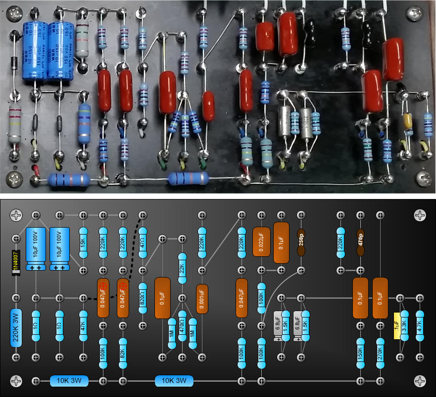
Phil, some final thoughts(for now ). I'm going to flip flop on the value of that first plate resistor. It looks like it could be 150k but it also looks like it could be 110k and as you pointed out, 110k makes a little more sense. Because of its size, I think the brown Paktron capacitor coming out of the clean to the 475k is more likely a .047 than .022.
The power tube grid resistors are probably 5.1k or 4.7k rather than the Fender 1.5k. Finally, the clean treble capacitor value 360pf ? Maybe that is a value that Aaron liked in his build but I don't see anything in the photos where that could be verified as the value in the Dumble amp. Sorry, one more. It looks like he moved over the bass pots for treble controls on both channels. So they would be a standard 20%or 30% rather than the 2-35 and both the bass controls look look the same to me, 1 meg.
CW
-
pompeiisneaks
- Site Admin
- Posts: 4244
- Joined: Sat Jan 14, 2017 4:36 pm
- Location: Washington State, USA
- Contact:
Re: Dumble Modded Bassman Layout/Schematic
I've updated the list that made sense, but..Charlie Wilson wrote: ↑Fri Oct 02, 2020 1:15 am Phil, some final thoughts(for now
The power tube grid resistors are probably 5.1k or 4.7k rather than the Fender 1.5k. Finally, the clean treble capacitor value 360pf ? Maybe that is a value that Aaron liked in his build but I don't see anything in the photos where that could be verified as the value in the Dumble amp. Sorry, one more. It looks like he moved over the bass pots for treble controls on both channels. So they would be a standard 20%or 30% rather than the 2-35 and both the bass controls look look the same to me, 1 meg.
CW
You seem to be stating that the 360pF is maybe wrong for clean treble cap, but what is right?
I don't follow the last 'one more' Are you saying the bass 1MA is now the treble? And what is the new value of the bass then?
~Phil
tUber Nerd!
-
Charlie Wilson
- Posts: 1140
- Joined: Thu Jan 23, 2014 7:32 pm
1 others liked this
Re: Dumble Modded Bassman Layout/Schematic
Phil, not saying the 360pf treble cap is wrong. Just saying that unless there are some other photos, I don't see how that value could have been verified. I suspect that is a value that Aaron like the sound of in his build. 360pf is a pretty non standard value for a ceramic disc. My guess is that Dumble used the stock 250pf but that is only a guess. As far as the pots, I know those pots with the plastic insert on the back. They are a standard(in the 60s) 250kA and were used as the bass control pots. I suspect Dumble moved them over to the treble control position and used 1 meg audio pots for the bass control(for this build). On the schematic, Aaron labels the treble controls linear probably because the jcm800 uses linear. Hope that makes sense.
CW
CW

Re: Dumble Modded Bassman Layout/Schematic
Hello -
Great progress ..
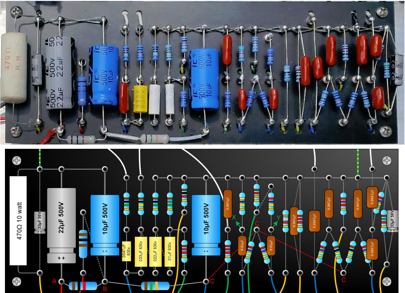
I was looking at the layout & schematics with eye to a proto build of just JCM flavour preamp. A small suggestion would be to draw consistently "at scale". Using your grid seems proportionate small 9 pin sockets vresus the size of the various passives -- for reference a 0.022 600V orange drop is ~0.75" long. A nit, but it helps visualization. Or it might be my eyes fooled, and you're using dimensional correct template symbols. On the schematic noting missing centre tap on secondary, for the ground. Might explain your KiCAD blocker.
Best .. Ian
Great progress ..
I was looking at the layout & schematics with eye to a proto build of just JCM flavour preamp. A small suggestion would be to draw consistently "at scale". Using your grid seems proportionate small 9 pin sockets vresus the size of the various passives -- for reference a 0.022 600V orange drop is ~0.75" long. A nit, but it helps visualization. Or it might be my eyes fooled, and you're using dimensional correct template symbols. On the schematic noting missing centre tap on secondary, for the ground. Might explain your KiCAD blocker.
Best .. Ian
-
pompeiisneaks
- Site Admin
- Posts: 4244
- Joined: Sat Jan 14, 2017 4:36 pm
- Location: Washington State, USA
- Contact:
Re: Dumble Modded Bassman Layout/Schematic
My understanding, is that these visio shapes, which came from sluckey, are all to scale. If they're not, I'm not even sure how to fix it exactly, I'd have to see if I can figure it out. Maybe a newer version of visio decided keeping things to scale was less important lol.didit wrote: ↑Mon Oct 05, 2020 3:48 pm Hello -
Great progress ..
I was looking at the layout & schematics with eye to a proto build of just JCM flavour preamp. A small suggestion would be to draw consistently "at scale". Using your grid seems proportionate small 9 pin sockets vresus the size of the various passives -- for reference a 0.022 600V orange drop is ~0.75" long. A nit, but it helps visualization. Or it might be my eyes fooled, and you're using dimensional correct template symbols. On the schematic noting missing centre tap on secondary, for the ground. Might explain your KiCAD blocker.
Best .. Ian
I'll see if I can add the center tap easily. Sorry was just going off of Aaron's schematic and missed that.
OH also in the photos I can see a ceramic cap between the anodes of the PI. But the angle makes it impossible to read... suggestions on the value? Is it needed ?
~Phil
tUber Nerd!
-
sluckey
- Posts: 3528
- Joined: Sun Jul 22, 2007 7:48 pm
- Location: Mobile, AL
- Contact:
3 others liked this
Re: Dumble Modded Bassman Layout/Schematic
My shapes are drawn to scale so a board layout can be done more accurately. A few small items like a diode are made slightly larger just so the writing will show up. Here's a pic of a layout and the actual board. I'd say pretty close. I actually use the Visio layout as a full size drilling template taped to the board.pompeiisneaks wrote: ↑Mon Oct 05, 2020 4:27 pm My understanding, is that these visio shapes, which came from sluckey, are all to scale. If they're not, I'm not even sure how to fix it exactly, I'd have to see if I can figure it out. Maybe a newer version of visio decided keeping things to scale was less important lol.
-
pompeiisneaks
- Site Admin
- Posts: 4244
- Joined: Sat Jan 14, 2017 4:36 pm
- Location: Washington State, USA
- Contact:
Re: Dumble Modded Bassman Layout/Schematic
I've added a BOM that I generated from the schematic in KiCAD.
I'm about to begin the build... Thoughts. Should I put the build thread/videos in their own thread or keep it in this one?
~Phil
I'm about to begin the build... Thoughts. Should I put the build thread/videos in their own thread or keep it in this one?
~Phil
tUber Nerd!
-
professormudd
- Posts: 405
- Joined: Thu Jul 16, 2020 6:53 pm
- Location: Southern California
1 others liked this
Re: Dumble Modded Bassman Layout/Schematic
I would find it easier to follow your build if it had a discrete thread.
-Matt
It may very well be that the sole purpose of your life is only to serve as a warning to others.
It may very well be that the sole purpose of your life is only to serve as a warning to others.
-
pompeiisneaks
- Site Admin
- Posts: 4244
- Joined: Sat Jan 14, 2017 4:36 pm
- Location: Washington State, USA
- Contact:
Re: Dumble Modded Bassman Layout/Schematic
Makes sense, thanks for the feedback professormudd
I've updated a few more errors. I was missing the 1.8k resistor in the tone stack on the normal channel. Fixed on both the schematic and the BOM. Removed a few unneeded entries on the BOM
~Phil
I've updated a few more errors. I was missing the 1.8k resistor in the tone stack on the normal channel. Fixed on both the schematic and the BOM. Removed a few unneeded entries on the BOM
~Phil
tUber Nerd!
-
Charlie Wilson
- Posts: 1140
- Joined: Thu Jan 23, 2014 7:32 pm
Re: Dumble Modded Bassman Layout/Schematic
Phil, I think that is a 6.8k standard Fender value. A 1.8k would be a mid control turned down pretty low. Interesting, looks like a Piher resistor.
CW
CW
-
pompeiisneaks
- Site Admin
- Posts: 4244
- Joined: Sat Jan 14, 2017 4:36 pm
- Location: Washington State, USA
- Contact:
Re: Dumble Modded Bassman Layout/Schematic
Ok, damn at least that came in the morning after I ordered all the parts I'd need
I will have to see if I have a 6.8k around, if not I can run to the local shop and get some.
I tried zooming into the only photo with that resistor and adjusted brightness/contrast etc, and man at that point I still can't see any colors.
~Phil
I will have to see if I have a 6.8k around, if not I can run to the local shop and get some.
I tried zooming into the only photo with that resistor and adjusted brightness/contrast etc, and man at that point I still can't see any colors.
~Phil
tUber Nerd!
-
pompeiisneaks
- Site Admin
- Posts: 4244
- Joined: Sat Jan 14, 2017 4:36 pm
- Location: Washington State, USA
- Contact:
Re: Dumble Modded Bassman Layout/Schematic
Back to this one gang. I'm almost done putting mine together, but I don't know which tap to connect my 100k NFB resistor to? I've got a multi tap 16/8/4 OT, but in the original I can't seem to see what it had/used? or what HAD used
Anyone know what a 100k NFB on an output stage like this one usually connected to? My WAG is 8ohm but... not sure.
~Phil
Anyone know what a 100k NFB on an output stage like this one usually connected to? My WAG is 8ohm but... not sure.
~Phil
tUber Nerd!
Re: Dumble Modded Bassman Layout/Schematic
Hello Phil
Dumble generally used the 4 ohm tap in the ODS ala Fender Twin and Pacific Marshall in #183
The Bassmans I've seen modded were 60's AB165's and those also have a 4 ohm tap..
Ideally you can use either tap. the higher the impedance the more GNFB gets feedback through the circuit due to the added turns.. We build amps so I would check out both 4 and 8 while you're at it, just to see which one sounds or better suits for your ears/speakers style and setup..
the 4 ohm tap will be brighter and looser have a little more gain and liveliness. The 8 ohm will be darker and the amp tighter on the low end..Do this with the amp cranked up so you get the full effect from the presence circuit. Let us know which one you prefer.
Tony
" The psychics on my bench is the same as Dumble'"