All,
I recently built a 102 clone and have some questions regarding my amp. I am in the infancy stages of amp building but purchased an oscilloscope to help me understand the signal and need some help understanding the data. I start with power supply questions because I figure the power to the tubes is most important but I’m most interested in question 2.
Power supply question:
Based on the 102 schematic, the dropping resistor values (and suggested approximate voltages) should be:
(B+1 450V) choke (B+2 450V) 2.7K (B+3 425V), 22K (B+4 320V), and 2.2K (B+5 310V).
My amp (originally):
(B+1 444V) choke (B+2 443V) 2.2K (B+3 430V), 22K (B+4 361V), and 2.2K (B+5 357V).
I have submitted one other post since building this amp in which I listed different voltages but after changing some capacitors and resistors, these were my “starting” voltages.
I changed dropping resistors and the current B+ voltages are:
(B+1 443V) choke (B+2 441V) 3.3K (B+3 426V), 36K (B+4 328V), and 2.2K (B+5 324V).
QUESTION 1:
I changed dropping resistor 1 from 2.2K to 3.3K and resistor 2 from 22K to 36K and the B+4&5 voltages are still too high. Is this typical or does the fact that I needed to change the second dropping resistor by so much suggest something is wrong elsewhere in the circuit?
Pre-amp questions
QUESTION 2
So, with B+4 328V, and B+5 324V (plate voltages V1A 197V, V1B 199V, V2A 208V, V2B 212V): The first image shows an 1KHz signal into 68K V2A grid stopper resistor (approximate 1KHz-my signal generator is from the 1980’s, cheap, and DC offset is close but not exactly zero). The second image is the same signal out of that resistor (into the grid). Why does the positive side of the signal get clipped through this resistor?
QUESTION 3
The third image is the same signal previously in the signal chain after V1B with volume pot turn up ¾. Is this typical signal clipping? Specifically, is the top signal a flat cutoff while the bottom is curved?
Being new to this I’m not sure if the signals I’m getting are typical or if they suggest I F*#%ed something up. Any suggestions and direction would be appreciated.
Thanks
Mark
102 build advice
Moderators: pompeiisneaks, Colossal
102 build advice
You do not have the required permissions to view the files attached to this post.
-
Charlie Wilson
- Posts: 1140
- Joined: Thu Jan 23, 2014 7:32 pm
Re: 102 build advice
Hello Mark,
What I would do, if possible, is post some clear gut shots of your amplifier and some background as far as what transformers are being used. Makes it easier for guys to help you sort out what is going on.
CW
What I would do, if possible, is post some clear gut shots of your amplifier and some background as far as what transformers are being used. Makes it easier for guys to help you sort out what is going on.
CW

Re: 102 build advice
Hi Mark,
Do you have the Fet circuit in your build?
If not that would explain the high voltages on B4 and B5.
Regarding the input signal: how much RMS voltage from the signal generator is injected at the input?
Erwin
Do you have the Fet circuit in your build?
If not that would explain the high voltages on B4 and B5.
Regarding the input signal: how much RMS voltage from the signal generator is injected at the input?
Erwin

Re: 102 build advice
As was already asked, what kind of voltage are you putting into the amp? The picture at the input VS output of the V2A 68K grid stopper is telling you the grid is going too positive and conducting. You don't want that. Either your input signal is too hot, or the tube is not biased correctly. Have you verified that Rp is 220K and Rk 3.3K, and that the V2A grid is at DC ground before you inject the signal??
Gil
Gil
cdale-amp wrote: ↑Sun Aug 11, 2019 2:40 am All,
I recently built a 102 clone and have some questions regarding my amp. I am in the infancy stages of amp building but purchased an oscilloscope to help me understand the signal and need some help understanding the data. I start with power supply questions because I figure the power to the tubes is most important but I’m most interested in question 2.
Power supply question:
Based on the 102 schematic, the dropping resistor values (and suggested approximate voltages) should be:
(B+1 450V) choke (B+2 450V) 2.7K (B+3 425V), 22K (B+4 320V), and 2.2K (B+5 310V).
My amp (originally):
(B+1 444V) choke (B+2 443V) 2.2K (B+3 430V), 22K (B+4 361V), and 2.2K (B+5 357V).
I have submitted one other post since building this amp in which I listed different voltages but after changing some capacitors and resistors, these were my “starting” voltages.
I changed dropping resistors and the current B+ voltages are:
(B+1 443V) choke (B+2 441V) 3.3K (B+3 426V), 36K (B+4 328V), and 2.2K (B+5 324V).
QUESTION 1:
I changed dropping resistor 1 from 2.2K to 3.3K and resistor 2 from 22K to 36K and the B+4&5 voltages are still too high. Is this typical or does the fact that I needed to change the second dropping resistor by so much suggest something is wrong elsewhere in the circuit?
Pre-amp questions
QUESTION 2
So, with B+4 328V, and B+5 324V (plate voltages V1A 197V, V1B 199V, V2A 208V, V2B 212V): The first image shows an 1KHz signal into 68K V2A grid stopper resistor (approximate 1KHz-my signal generator is from the 1980’s, cheap, and DC offset is close but not exactly zero). into V2A grid stopper resistor 68K.pngThe second image is the same signal out of that resistor (into the grid). Why does the positive side of the signal get clipped through this resistor? out V2A grid stopper resistor 68K-into grid.png
QUESTION 3
The third image is the same signal previously in the signal chain after V1B with volume pot turn up ¾. Is this typical signal clipping? Specifically, is the top signal a flat cutoff while the bottom is curved? V1B out-vol 0.75 clipping.png
Being new to this I’m not sure if the signals I’m getting are typical or if they suggest I F*#%ed something up. Any suggestions and direction would be appreciated.
Thanks
Mark
Re: 102 build advice
Thanks for the replies.
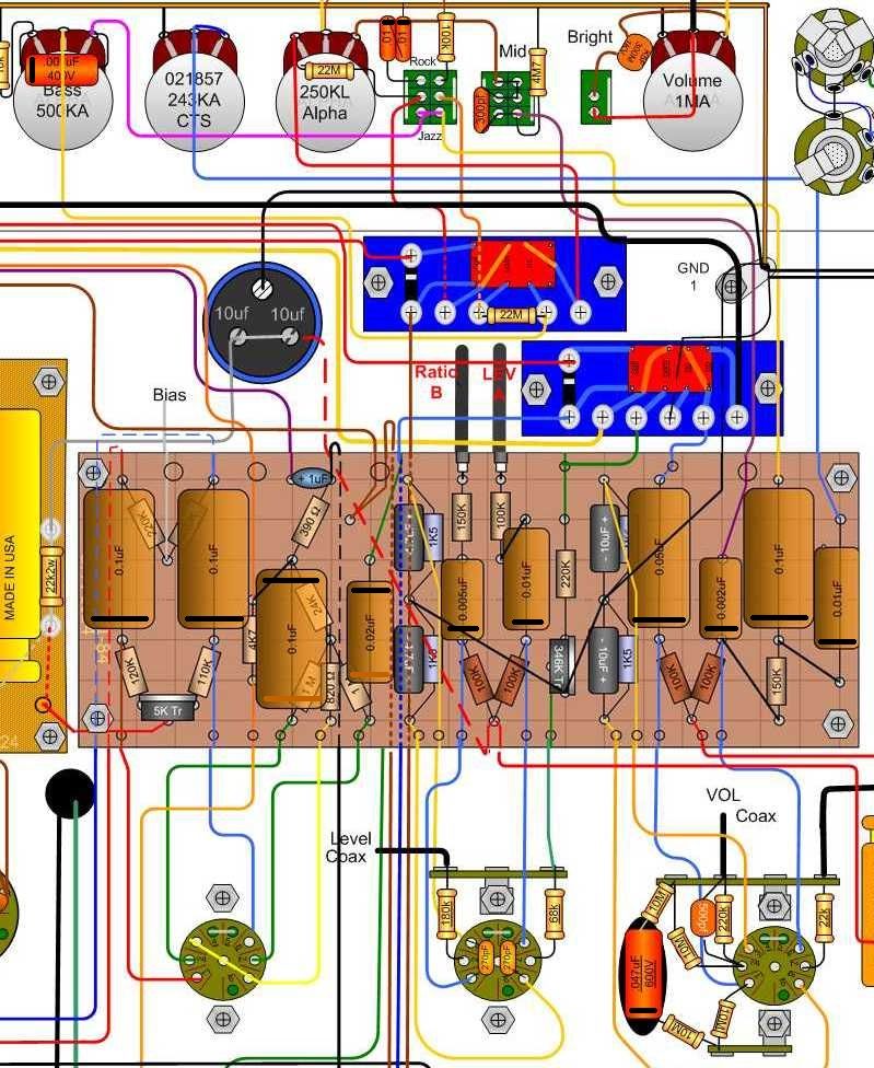
"Gut shots" bellow. A few things regarding my build:
1. This is my first build so I'm just starting to figure this out. Please feel free to give constructive criticism.
2. Re components, I read about the different opinions but decided to go with metal film resistor as opposed to carbon, and polypropylene capacitors as opposed to orange drops. If you feel strongly that this was a mistake please let me know why. I believe all resistors are higher wattage than necessary, I went conservative with my selections.
3. I went supper conservative with my power supply resistors, 10W originally. These are way larger than I thought so I needed to redesign the layout. A bit messy but it's made swapping dropping resistors fairly easy.
4. It is 99% the 102 I found on this site. https://ampgarage.com/forum/download/fi ... &mode=view
5. transformers are Classic Tone, same specs as on schematic, at least I'm fairly sure that is true. PT is 40-18004 and OT is 40-18013. Erwin, no FET, thanks for the information, I did not know that circuit drew enough power to change B+ by that much. Super helpful info.
For the oscilloscope signals, the input voltage was around 500mV RMS.
Gil, thanks for explanation, but I'm not entirely sure how to fix my "grid going too positive". I verified Rp is 220K and Rk 3.3K. Could the signal be too large due to an improperly set OD trim pot? Currently it is 40K ohms (if you look for this pot in the photos I bought the wrong kind, hate it and need to replace it). I do not entirely understand what you mean by "have you verified.....the V2A grid is at DC ground before you inject the signal"? The grid is grounded via OD trim pot, if that is what you are asking (grid to ground resistance is 40.4K ohms if that helps).
Thanks for the help thus far. I built this amp so I could change things, take measurements, make mistakes, etc to help me better understand tube amps. It's still a bit over my head but having and actual circuit has helped me better understand all of the theory I've read over the last year.
Mark
You do not have the required permissions to view the files attached to this post.
Re: 102 build advice
The resistance between the grid and ground cannot actually be 40+K if you have a 68K grid stopper. It should be about 108K, and based on what you said, I think will check out OK. One question that was asked by someone else and then by me is how many volts do you have at the input of the 68K resistor? Also, be sure you know if the scope probe is at to x1 or x10 mode so that you know whether your reading needs to be scaled or not. You can always check the AC line with the scope to make sure you know what scale it’s using. It'll probably check out OK too, but it can't hurt to make sure there are no bugs. Just to eliminate the possibility of a bad tube, have you tried a different 12AX7 in V2? If all of these things check out, maybe you can measure the V2A output after the .01 uF coupling cap. Start with you input signal at zero V. Your output should be 0 as well. Then, as you bring the input signal up, slowly, the V2A output should not be distorted. As you continue to turn up the signal level, you should see the top of the output signal get a little squashed. That would mean that the grid has gotten as negative as it will go, so you are seeing the output reflect that.
You want to be able to see the behavior described above. When the output of the first stage that’s distorting at all clips both the top and the bottom, it means that the tube is saturating (grid bottoming out on the negative cycle), and that the grid is also conducting on the positive cycle as well. You do not want any stage to do this. Each stage should distort the signal a little bit, showing a flattened top at the output. The next stage will clip the other side of the wave, etc. Hope this helps.
You want to be able to see the behavior described above. When the output of the first stage that’s distorting at all clips both the top and the bottom, it means that the tube is saturating (grid bottoming out on the negative cycle), and that the grid is also conducting on the positive cycle as well. You do not want any stage to do this. Each stage should distort the signal a little bit, showing a flattened top at the output. The next stage will clip the other side of the wave, etc. Hope this helps.
Last edited by ayan on Mon Aug 12, 2019 3:30 pm, edited 1 time in total.
Re: 102 build advice
Mark, to simulate the load of the fet add a 150k resistor from B+5 to ground.
I'm with Gil om the above.
Erwin
I'm with Gil om the above.
Erwin

Re: 102 build advice
Looks like the trimmer is set too high.
Also do the outer foil orientation like this post.
https://ampgarage.com/forum/viewtopic.php?f=4&t=24654
http://i932.photobucket.com/albums/ad16 ... Foil-2.jpg
Also do the outer foil orientation like this post.
https://ampgarage.com/forum/viewtopic.php?f=4&t=24654
http://i932.photobucket.com/albums/ad16 ... Foil-2.jpg
Re: 102 build advice
That is a bit high maybe. I use 100mV AC 1kHz.