I have a request to build an Altec 468c compressor. The customer would like DC filaments and I am wondering how to calculate the no-load voltage needed for the filament tap.
The tubes are:
12AY7 - 12.6v @ .15A or 6.3v @ .3A
6BC8 - 6.3v @ .4A
6CG7 - 6.3v @ .6A
6AL5 - 6.3v @ .3A
I listed the 12v draw of the 12AY7 although I can't see that being relevant... the different current loads prevent any kind of parallel configuration. I found this out the hard way.
This topic comes up quite often in my little local group of tube nerds. I don't want someone to give me a fish, maybe just teach me to fish...? Is there a source of info about this type of calculation that could be posted here? I'm having fun learning all about the intricacies of transformers and anything to read that would point the way would be much appreciated.
Side note: If you remove the 6AL5 diode tube then the unit becomes just a preamp. The version on my bench has separate inputs to the first two tubes so that it can be used for a mic preamp or a line level input. This is a very useful thing and with some mods can be quite a great unit. Thinking of two of these in stereo...
Thanks in advance,
Tony
(edited my bonehead mistake)
DC Filament No-Load Calculation
Moderators: pompeiisneaks, Colossal
-
dorrisant

- Posts: 2790
- Joined: Tue Sep 21, 2010 1:27 pm
- Location: Somewhere between a river and a cornfield
- Contact:
DC Filament No-Load Calculation
You do not have the required permissions to view the files attached to this post.
Last edited by dorrisant on Tue Apr 14, 2015 6:43 pm, edited 1 time in total.
"Education is what you're left with after you have forgotten what you have learned" - Enzo

Re: DC Filament No-Load Calculation
All the currents you wrote are in Ampère, not mA.
If you go DC, use a voltage regulator (EG the LM317) plus of course a Transistor to increase the available current.
If you go DC, use a voltage regulator (EG the LM317) plus of course a Transistor to increase the available current.
-
dorrisant
- Posts: 2790
- Joined: Tue Sep 21, 2010 1:27 pm
- Location: Somewhere between a river and a cornfield
- Contact:
Re: DC Filament No-Load Calculation
Yes you are absolutely right! I will edit to reflect that.roberto wrote:All the currents you wrote are in Ampère, not mA.
I should have specified that I was looking for an unregulated circuit, but do you have an example of what you mentioned?
Tony
"Education is what you're left with after you have forgotten what you have learned" - Enzo
Re: DC Filament No-Load Calculation
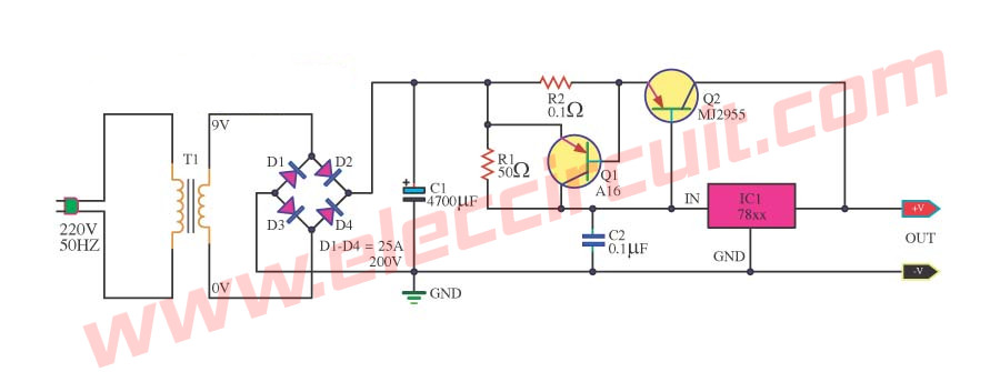
[img:900:335]http://www.eleccircuit.com/wp-content/u ... ircuit.jpg[/img]
This circuit can handle 5 A (Q2) and has a short circuit protection (Q1).
This circuit can handle 5 A (Q2) and has a short circuit protection (Q1).
Re: DC Filament No-Load Calculation
Why do you think that?the different current loads prevent any kind of parallel configuration.
In fact, even in the Altec schematic they are shown all in parallel, even the 12A*7 .
You need a supply which can give you stable, regulated 6.3V DC and with enough current capacity for all fiklaments ... in parallel.
Just add up the individual currents.
Re: DC Filament No-Load Calculation
You can obtain it with a 7805 plus two diodes in series from the central pin to ground: 5+0,6+0,6 = 6,2V
-
dorrisant
- Posts: 2790
- Joined: Tue Sep 21, 2010 1:27 pm
- Location: Somewhere between a river and a cornfield
- Contact:
Re: DC Filament No-Load Calculation
Sorry, meant to type "series parallel", had a brain fart. The fellow I was doing a clone for mistakenly bought a PT with 12.6vac filament tap. He paid me to "go ahead and try that". He also paid me to fix it as well.JMFahey wrote:Why do you think that?the different current loads prevent any kind of parallel configuration.
In fact, even in the Altec schematic they are shown all in parallel, even the 12A*7 .
You need a supply which can give you stable, regulated 6.3V DC and with enough current capacity for all fiklaments ... in parallel.
Just add up the individual currents.
Roberto, I will try that with the diodes! Still learning here, thanks guys.
Tony
"Education is what you're left with after you have forgotten what you have learned" - Enzo
Re: DC Filament No-Load Calculation
In reference to Roberto's scheme, make sure R2 is a flame proof power resistor of several watts.
Is the current capability not 6 amps as shown? (Dividing the transistor "drop" of Q1 of 0.6 / current sense resistor R2) 0.6/0.1 = 6 amps ??
Is the current capability not 6 amps as shown? (Dividing the transistor "drop" of Q1 of 0.6 / current sense resistor R2) 0.6/0.1 = 6 amps ??
Re: DC Filament No-Load Calculation
6 is on the edge, I'd suggest five, or use two transistors in parallel.
-
dorrisant
- Posts: 2790
- Joined: Tue Sep 21, 2010 1:27 pm
- Location: Somewhere between a river and a cornfield
- Contact:
Re: DC Filament No-Load Calculation
Roberto, for Q1 above you have it listed as SA16. Is that like a 2SA1667? Or what would work? Pardon my ignorance.
Tony
Tony
"Education is what you're left with after you have forgotten what you have learned" - Enzo
Re: DC Filament No-Load Calculation
A 2N6049 will go.
Check the datasheet of the 7812:
http://www.onsemi.com/pub_link/Collateral/MC7800-D.PDF
Check the datasheet of the 7812:
http://www.onsemi.com/pub_link/Collateral/MC7800-D.PDF
DC heater voltage
I checked the dc heater voltage on a Peavey 6505+ combo and read 7.1 v on each of the pre amp tubes. Could that make the amp sound bad or is that the way it normally sounds? Harsh cleans and extremely high compression on the od channels. Probably just not my style of amp, but this one doesn't appeal to me at all. For sale cheap
Re: DC Filament No-Load Calculation
I would check the bias instead.
Re: DC Filament No-Load Calculation
I can do that right now, actually. Just got a bias tester and haven't used it yet. The amp did come with new replacement JJ's so maybe it's way off.
Re: DC Filament No-Load Calculation
Running only one Ruby 6l6gmcstr at a time, with the srs ma tester, I get 55ma, and 60 ma in the other socket. Way to high for a 6505+ combo. And no bias adjustment. My bias voltage, as I remember was 51 volts, so maybe I'll try new tubes, again.