Maximizing headroom in an LTP PI

General discussion area for tube amps.

Moderators: pompeiisneaks, Colossal

User avatar
Lynxtrap
Posts: 354
Joined: Fri Feb 18, 2011 12:37 pm
Location: EU

Maximizing headroom in an LTP PI

Post by Lynxtrap »

I've been reading some theory about this, and I understand that some of it is the same as applied to a triode gainstage. But I'd still appreciate some, let's says, more hands-on advice.

The question is, how do we achieve maximum headroom in a long tail pair PI, while keeping maximum swing and/or output from the PI? That is, minimizing distortion in the PI itself while pushing the output stage.

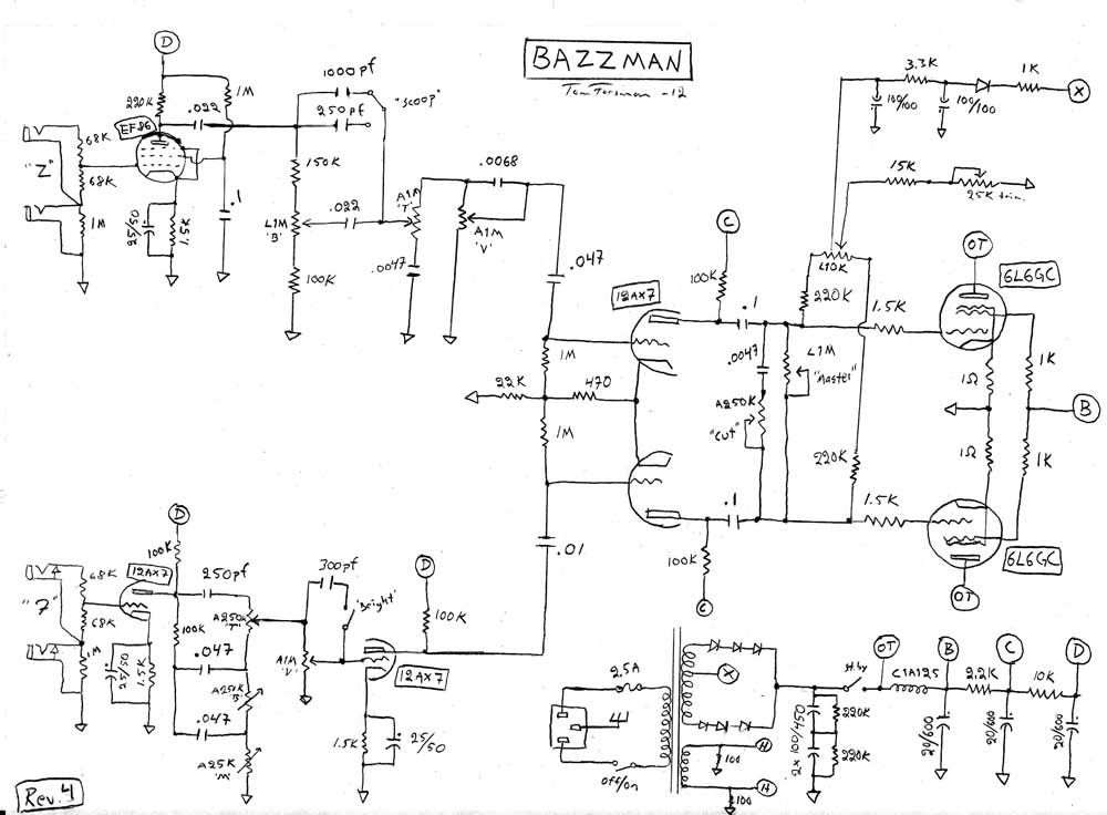
I'm speaking in general, but I will use the particular schematic below as reference, since that is the amp with the problem at hand. It might also be that input on both sides of the PI changes the game (that's one of the things I don't know...)

[img:1000:736]http://i1181.photobucket.com/albums/x43 ... 4_webb.jpg[/img]
User avatar
roberto
Posts: 1841
Joined: Tue Nov 27, 2007 4:45 pm
Location: Italy

Re: Maximizing headroom in an LTP PI

Post by roberto »

To obtain more headroom you have to:
- remove the 1M log pot PPIMV
- substitute 1k screen resistors with 470R
- try also 10k instead of 22k tail resistor
User avatar
chief mushroom cloud
Posts: 429
Joined: Tue Jan 18, 2005 5:42 pm
Location: Peenemunde CA

Re: Maximizing headroom in an LTP PI

Post by chief mushroom cloud »

you can change your B+ dropping resistors to get a good size change in headroom on the PI
change the 2.2k to a 1k and change 10k to 11k (or whatever value gets you +290V on D)
Don't overthink it. Just drink it.
User avatar
VacuumVoodoo
Posts: 924
Joined: Fri Feb 17, 2006 6:27 pm
Location: Goteborg, Sweden
Contact:

Re: Maximizing headroom in an LTP PI

Post by VacuumVoodoo »

Just connect the 22k tail resistor tot the negative raw bias voltage, instead of ground.
Aleksander Niemand
------------------------
Life's a party but you get invited only once...
affiliation:TUBEWONDER AMPS
Zagray!-review
User avatar
roberto
Posts: 1841
Joined: Tue Nov 27, 2007 4:45 pm
Location: Italy

Re: Maximizing headroom in an LTP PI

Post by roberto »

chief, you have around 6mA flowing into that 2k2.
It won't change anything if you drop 6volt more, but you'll decrease separation from screens, and this could not be a good idea.

Vacuum, raw bias is a good idea, because you'll gain around 50V, but you have to be sure is well filtered at the point you connect the PI.
User avatar
rdjones
Posts: 818
Joined: Tue Aug 31, 2010 2:20 am
Location: Music City, TN

Re: Maximizing headroom in an LTP PI

Post by rdjones »

The PI circuit has several issues that affect headroom and distortion.
No NFB, not tuned for balance, and tube type contribute to imbalance and distortion.
Maximum headroom occurs when there is a high degree of balance in the PI outputs.
I'd wager that driving the PI grids separately without a mixer and without a solid AC ground reference for the opposing grid increases the already inherent imbalance of the LTP.
What kind of voltage is on the plates ?

rd
User avatar
roberto
Posts: 1841
Joined: Tue Nov 27, 2007 4:45 pm
Location: Italy

Re: Maximizing headroom in an LTP PI

Post by roberto »

I suppose something around 400-420V on plates and screens, 400V on PI and 350V on preamp.
User avatar
Structo
Posts: 15446
Joined: Wed Oct 17, 2007 1:01 am
Location: Oregon

Re: Maximizing headroom in an LTP PI

Post by Structo »

VacuumVoodoo wrote:Just connect the 22k tail resistor tot the negative raw bias voltage, instead of ground.
So this allows more voltage swing, thereby increasing head room?

Just trying to understand as I haven't heard of that method before.
Sounds easy enough to do.
Tom

Don't let that smoke out!
Cliff Schecht
Posts: 2629
Joined: Wed Dec 30, 2009 7:32 am
Location: Austin
Contact:

Re: Maximizing headroom in an LTP PI

Post by Cliff Schecht »

roberto wrote:chief, you have around 6mA flowing into that 2k2.
It won't change anything if you drop 6volt more, but you'll decrease separation from screens, and this could not be a good idea.

Vacuum, raw bias is a good idea, because you'll gain around 50V, but you have to be sure is well filtered at the point you connect the PI.
It's feeding a push-pull stage so filtering probably isn't as critical as you'd think. The CMRR of this stage is usually high enough to tolerate some rail noise (assuming the triodes are decently matched in the PI).
Structo wrote:
VacuumVoodoo wrote:Just connect the 22k tail resistor tot the negative raw bias voltage, instead of ground.
So this allows more voltage swing, thereby increasing head room?

Just trying to understand as I haven't heard of that method before.
Sounds easy enough to do.
It gives you more negative V to swing which effectively increases the headroom before clipping (assuming here that power tube grid conduction doesn't cause PI clipping).
Cliff Schecht - Circuit P.I.
User avatar
VacuumVoodoo
Posts: 924
Joined: Fri Feb 17, 2006 6:27 pm
Location: Goteborg, Sweden
Contact:

Re: Maximizing headroom in an LTP PI

Post by VacuumVoodoo »

roberto wrote: Vacuum, raw bias is a good idea, because you'll gain around 50V, but you have to be sure is well filtered at the point you connect the PI.
Not necessarily. I've been doing this for years. Any ripple on the raw bias is seen by LTPI as common mode signal. LTPI being a basic differential pair has a pretty decent CMMR (common mode rejection ratio) for a guitar amp.
It wouldn't be good enough in a front of a 24bit ADC or even a 16bit .
However, you'll be sinking ca 1.5-2mA into the bias resistor chain so you'll need to readjust your power tubes idling current.
Aleksander Niemand
------------------------
Life's a party but you get invited only once...
affiliation:TUBEWONDER AMPS
Zagray!-review
Cliff Schecht
Posts: 2629
Joined: Wed Dec 30, 2009 7:32 am
Location: Austin
Contact:

Re: Maximizing headroom in an LTP PI

Post by Cliff Schecht »

Read right above your last post Aleks ;).

With your typical 5% tolerance resistors and again assuming well balanced/matched triodes you can expect at least 20B of CMRR which is good enough for a lot of non-critical applications. In our case since the SNR of this stage is so high anyways (low gain and very late in the signal chain) the common-mode rejection can be quite low and yet still adequate with enough power supply filtering.
Cliff Schecht - Circuit P.I.
User avatar
VacuumVoodoo
Posts: 924
Joined: Fri Feb 17, 2006 6:27 pm
Location: Goteborg, Sweden
Contact:

Re: Maximizing headroom in an LTP PI

Post by VacuumVoodoo »

Missed that, Cliff. Good catch. I was in the middle of restoring an old Laney Klipp 60 that burned out a PT and some other stuff. It's now in better condition than when it left factory in 1972 :D
Aleksander Niemand
------------------------
Life's a party but you get invited only once...
affiliation:TUBEWONDER AMPS
Zagray!-review
User avatar
Lynxtrap
Posts: 354
Joined: Fri Feb 18, 2011 12:37 pm
Location: EU

Re: Maximizing headroom in an LTP PI

Post by Lynxtrap »

Thanks for all the answers :) The bias method sounds interesting. By "raw" bias, do you mean connecting to the bias supply before the pot?
I don't doubt it works, but won't the negative voltage cause an extremely cold bias that could affect the sound?

As to the voltages, I have close to 300 at the PI plates.
I should add that I'm now running a 12AT7, not AX7 as noted in the schematics.

Can't comment on all the post, but rdjones has got me a bit puzzled. I don't see why this PI would be particularly unbalanced. And why would that decrease headroom?
Roe
Posts: 1918
Joined: Thu May 31, 2007 2:10 pm

Re: Maximizing headroom in an LTP PI

Post by Roe »

use the silverface PI with 12at7, 47k plate resistors, 270k cathode, 15k tail, 330Ks, and around 300v at the plates of the 12at7
www.myspace.com/20bonesband
www.myspace.com/prostitutes
Express, Comet 60, Jtm45, jtm50, jmp50, 6g6b, vibroverb, champster, alessandro rottweiler
4x12" w/H75s
User avatar
erwin_ve
Posts: 1792
Joined: Fri Jan 25, 2008 8:06 am
Location: Dordrecht, Netherlands
Contact:

Re: Maximizing headroom in an LTP PI

Post by erwin_ve »

VacuumVoodoo wrote:Just connect the 22k tail resistor tot the negative raw bias voltage, instead of ground.
Very interesting, how would you implement something like this when there is GNFB connected to the 22k? Any side effects besides increased headroom?
Post Reply