I also included the mod described e.g. on the second page of this thread
https://tubeamparchive.com/viewtopic.ph ... sc&start=0
and shown in this image (the additional 500p between the plate of V1a and the unused pin of the upper PAB relay).
[img:883:758]http://img.photobucket.com/albums/v21/m ... Fatmod.gif[/img]
The schemo I used for the sims is more or less like the above schem. Only difference 22M PAB resistors and negative feedback loop at V1b.
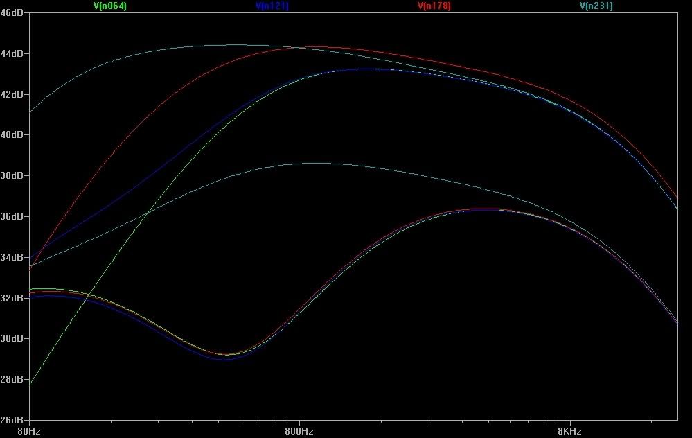
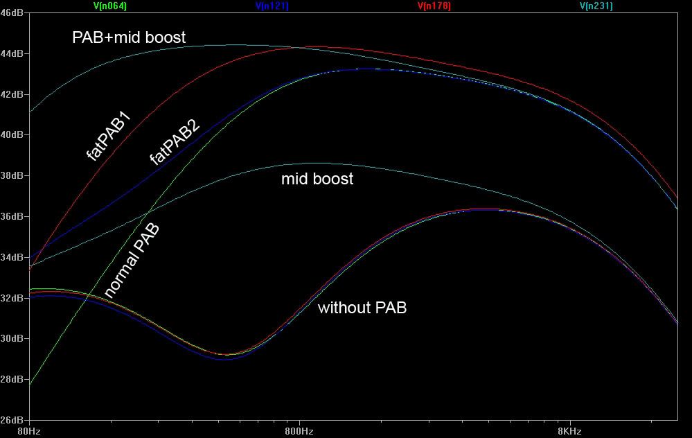
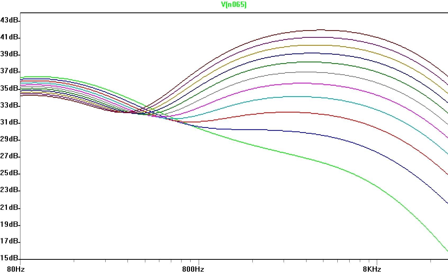
Here's an image of the simulations with the frequency response at V1b plate.
[img:999:632]http://img.photobucket.com/albums/v21/m ... rd01-1.jpg[/img]
Starting at the bottom of the left Y-axis:
green: "normal" PAB
Blue, red and green (more or less overlapping): without PAB, treb, bass, mid all at 50%
Light blue: mid boost
Red: fat PAB mod as shown in the schem above, just with 220p; increases bottom end but also slightly overall PAB level (compared to normal PAB)
Blue: fat PAB by replacing the 500p (or actually 220p) with a 2M2 resistor as shown in the schem below. Bottom end increases but high end remains the same as with "normal" PAB
If the resistor is decreased to 1M bottom end further increases but highs remain unchanged. Increasing the 2M2 shifts bottom end down towards "normal" PAB. A 5M trim pot I believe should give a reasonable range.
Top light blue: normal PAB plus mid boost (just for completeness)
[img:883:758]http://img.photobucket.com/albums/v21/m ... atmod2.gif[/img]
BTW, I checked removing the NFB at V1b. Didn't make a significant difference on the relative levels of the various curves.
The difference between the two "fat PAB" mods isn't huge. Nevertheless it might be worth a try to test the "resistor" variant, because only the bottom end is increased and the mod reqires shorter wires for the connections (from mid boost switch or mid boost relay to PAB relay)...FWIW
Let me know what you think
Peace,
Markus

 1033]
1033]