Fet Jack
Moderators: pompeiisneaks, Colossal
Fet Jack
Hey all, I just picked up a stereo 2 switch jack today for the fet input on my clone that I've been working on for awhile now and was wanting to know if most brands are the same or not.the one I have is almost identical to the one on #124 here http://i55.photobucket.com/albums/g159/ ... 1261612843 but I was not sure if I should wire it up the same.I got it at a local electronics store and don't know the brand of it. I have looked at the ones on mouser, they are close to mine but not exact. I have took my multi meter and tried to figure the rings,tips and such only to get confused (Have some knowledge but I guess not enough  ). I could not find the other kind of jacks that I have seen most here use and don't need enough parts to order from mouser or others to make it worth the $ for S&H. Any help is greatly apreceated. I don't have far to go on this so hope I can figure it out soon. Thanks, Chad

Re: Fet Jack
it's a stereo jack TRS. you can make a test unit by plugging a TRS lack in and using a multi meter to test continuity. draw the back as you see it and label the results. test with the jack inserted and out... the posts to themselves... this will tell you which ones are the switching posts and which are constant hots.
the other idea contact the manufacture and ask for a wiring diagram.
the other idea contact the manufacture and ask for a wiring diagram.
My Daughter Build Stone Henge
-
UltraHookedOnPhonix

- Posts: 414
- Joined: Thu Dec 15, 2005 9:32 pm
- Location: Dumbleland
Re: Fet Jack
Hi Chad!
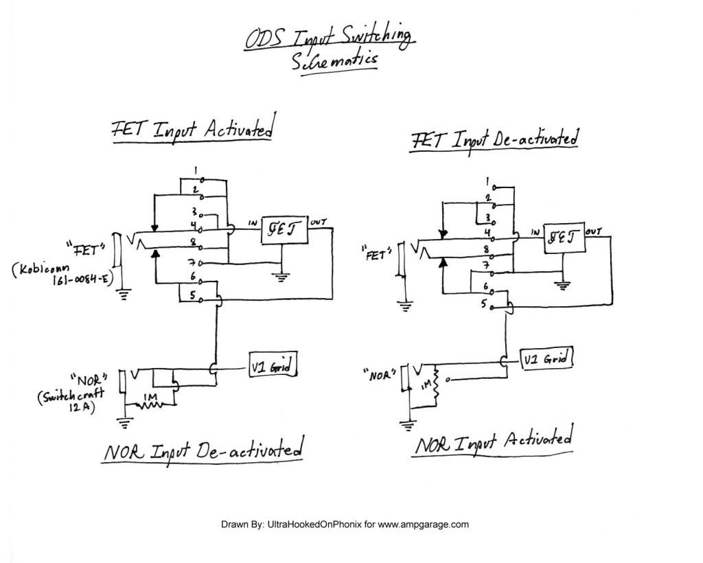
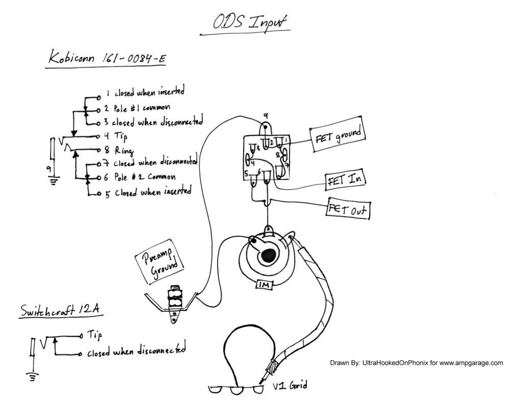
Here's two drawings I made of the input switching system. This is how it appears in the ODS. Remember to isolate the NOR and FET jacks from the chassis. The schematic and layout shown are for the Kobiconn 161-0084-E (http://mouser.com/ProductDetail/Kobicon ... yOLQ%3d%3d)
Be forewarned however, that the jack listed doesn't "hug" the plug all that well. I'm sure there are other manufacturers though.
[IMG 820]http://i205.photobucket.com/albums/bb17 ... matics.jpg[/img]
[IMG792]http://i205.photobucket.com/albums/bb17 ... Layout.jpg[/img]
Here's two drawings I made of the input switching system. This is how it appears in the ODS. Remember to isolate the NOR and FET jacks from the chassis. The schematic and layout shown are for the Kobiconn 161-0084-E (http://mouser.com/ProductDetail/Kobicon ... yOLQ%3d%3d)
Be forewarned however, that the jack listed doesn't "hug" the plug all that well. I'm sure there are other manufacturers though.
[IMG
 820]http://i205.photobucket.com/albums/bb17 ... matics.jpg[/img]
[IMG
792]http://i205.photobucket.com/albums/bb17 ... Layout.jpg[/img]
Re: Fet Jack
For the newbees who may be confused by this thread - here's an alternate way:
You do not have the required permissions to view the files attached to this post.
Former owner of Music Mechanix
www.RedPlateAmps.com
www.RedPlateAmps.com

Re: Fet Jack
14B jacks are the way to go!
Re: Fet Jack
Thanks all,with the info I have here I should be able to figure it out (ShouldUltraHookedOnPhonix wrote:Hi Chad!
Here's two drawings I made of the input switching system. This is how it appears in the ODS. Remember to isolate the NOR and FET jacks from the chassis. The schematic and layout shown are for the Kobiconn 161-0084-E (http://mouser.com/ProductDetail/Kobicon ... yOLQ%3d%3d)
Be forewarned however, that the jack listed doesn't "hug" the plug all that well. I'm sure there are other manufacturers though.
[IMG
[IMG
-
martin manning

- Posts: 14308
- Joined: Sun Jul 06, 2008 12:43 am
- Location: 39°06' N 84°30' W
Re: Fet Jack
Looks like the data sheet for the Kobicon 161-0084-E (download from Mouser) has errors in the terminal numbering. Your layout looks correct and squares with #124, except that the input coax's shield is grounded at the Normal jack's sleeve terminal rather than at V1.UltraHookedOnPhonix wrote:Hi Chad!
Here's two drawings I made of the input switching system. This is how it appears in the ODS. Remember to isolate the NOR and FET jacks from the chassis. The schematic and layout shown are for the Kobiconn 161-0084-E (http://mouser.com/ProductDetail/Kobicon ... yOLQ%3d%3d)
Be forewarned however, that the jack listed doesn't "hug" the plug all that well. I'm sure there are other manufacturers though.
Another alternate arrangement is to use Switchcraft's 13E for the FET input as shown below, along with the scematic for the layout heisthl posted. Gil gets credit for suggesting the 13E, as I noticed one in his "last amp."
MPM
You do not have the required permissions to view the files attached to this post.
Re: Fet Jack
Another tip for the Newbies..It's good practice to try and ground your shielded wire to the source..This holds true throughout the amp and loop if you have one..Good Luck..
Tony
Tony
-
UltraHookedOnPhonix
- Posts: 414
- Joined: Thu Dec 15, 2005 9:32 pm
- Location: Dumbleland
Re: Fet Jack
I didn't draw this with #124 in mind (althought the FET wiring is exactly the same for any ODS amp as far as I know). In many later generation ODS amps, the input coax's shield is grounded at the Grid of V1 just like Larry Carltons #118 which looks like it's been updated several times.Your layout looks correct and squares with #124, except that the input coax's shield is grounded at the Normal jack's sleeve terminal rather than at V1.
You do not have the required permissions to view the files attached to this post.
Re: Fet Jack
Yeah, I've noticed that too.
Brown Note originally has the coax grounded like that at the V1a middle lug of the terminal strip which is grounded.
But it is common practice as Tony noted to ground the shield at the source of the signal.
Brown Note originally has the coax grounded like that at the V1a middle lug of the terminal strip which is grounded.
But it is common practice as Tony noted to ground the shield at the source of the signal.
Tom
Don't let that smoke out!
Don't let that smoke out!
-
martin manning
- Posts: 14308
- Joined: Sun Jul 06, 2008 12:43 am
- Location: 39°06' N 84°30' W
Re: Fet Jack
Of course you mean grounded to the chassis at V1... V1a's grid is ground-referenced by the 1M across the Normal input jack.UltraHookedOnPhonix wrote:...In many later generation ODS amps, the input coax's shield is grounded at the Grid of V1 just like Larry Carltons #118 which looks like it's been updated several times.
Perhaps in this case it really doesn't matter which end is grounded, since the shield is connected directly to chassis ground either way. Still, I'd have thought that the input jack end is "more direct" than the V1 end.
MPM
-
UltraHookedOnPhonix
- Posts: 414
- Joined: Thu Dec 15, 2005 9:32 pm
- Location: Dumbleland
Re: Fet Jack
But earlier you said the same thing! “…the input coax's shield is grounded at the Normal jack's sleeve terminal rather than at V1.”Of course you mean grounded to the chassis at V1... V1a's grid is ground-referenced by the 1M across the Normal input jack.
In our discussion, we were both referencing the location of where the coax shield grounds. Nothing wrong with that and it certainly didn’t present any confusion as the layout I drew clearly depicts where it grounds (which you inaccurately asserted was incorrect).
I think it’s fairly obvious that Dumble thought it mattered since he switched from doing what #124 did to consistently doing what the layout above shows. I think that demonstrates clear intent.Perhaps in this case it really doesn't matter which end is grounded, since the shield is connected directly to chassis ground either way. Still, I'd have thought that the input jack end is "more direct" than the V1 end.
Re: Fet Jack
Anybody done the old A/B thing to see if there is an audible difference?
Is a grid leak resistor the same thing as a ground?
Is a grid leak resistor the same thing as a ground?
Tom
Don't let that smoke out!
Don't let that smoke out!
-
martin manning
- Posts: 14308
- Joined: Sun Jul 06, 2008 12:43 am
- Location: 39°06' N 84°30' W
Re: Fet Jack
Not trying to start an argument here, sorry if it appears that way in print. I said your drawing matched #124's input wiring except for the shield ground location, but didn't say anything about which was correct or incorrect.UltraHookedOnPhonix wrote:But earlier you said the same thing! “…the input coax's shield is grounded at the Normal jack's sleeve terminal rather than at V1.”Of course you mean grounded to the chassis at V1... V1a's grid is ground-referenced by the 1M across the Normal input jack.
In our discussion, we were both referencing the location of where the coax shield grounds. Nothing wrong with that and it certainly didn’t present any confusion as the layout I drew clearly depicts where it grounds (which you inaccurately asserted was incorrect).
I think it’s fairly obvious that Dumble thought it mattered since he switched from doing what #124 did to consistently doing what the layout above shows. I think that demonstrates clear intent.Perhaps in this case it really doesn't matter which end is grounded, since the shield is connected directly to chassis ground either way. Still, I'd have thought that the input jack end is "more direct" than the V1 end.
I have few photos to examine, but I have one tagged #094 which uses the V1 terminal strip location for both the V1a and V1b shield grounds, where the #118 photo you posted shows only the V1a shield grounded there.
So, we have one shield ground configuration in #124, another in #118, and another in #094. I guess you're saying here that at some point (post-#124) HAD standardized on grounding the input coax shield at the V1 terminal strip, and that #118 was updated to that configuration at some point? Seems like the trend was towards moving the shield grounds over to the input side.
MPM
-
UltraHookedOnPhonix
- Posts: 414
- Joined: Thu Dec 15, 2005 9:32 pm
- Location: Dumbleland
Re: Fet Jack
No sweat! For a second I thought this discussion was heading towards this:Not trying to start an argument here, sorry if it appears that way in print. I said your drawing matched #124's input wiring except for the shield ground location, but didn't say anything about which was correct or incorrect.
www.youtube.com/watch?v=teMlv3ripSM
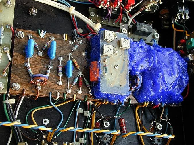
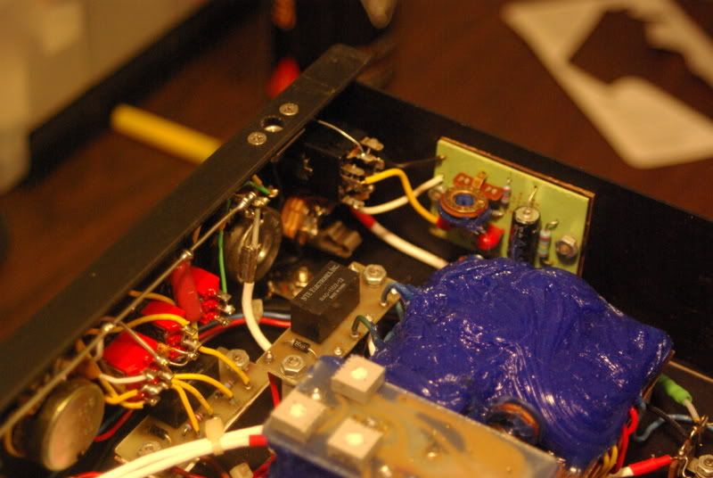
I certainly think that with the emergence of the HRM circuit, amps with serial numbers in the late #170’s started to routinely ground the input coax at the terminal strip in front of V1. I haven’t seen one HRM not do this. Here’s pics ranging from amps with serials ranging from #195 (nonHRM)-#234:So, we have one shield ground configuration in #124, another in #118, and another in #094. I guess you're saying here that at some point (post-#124) HAD standardized on grounding the input coax shield at the V1 terminal strip, and that #118 was updated to that configuration at some point? Seems like the trend was towards moving the shield grounds over to the input side.
[IMG:675:506]http://i205.photobucket.com/albums/bb17 ... ownODS.jpg[/img]
[IMG:800:536]http://i205.photobucket.com/albums/bb17 ... /97ODS.jpg[/img]
[IMG
768]http://i205.photobucket.com/albums/bb17 ... /234-1.jpg[/img]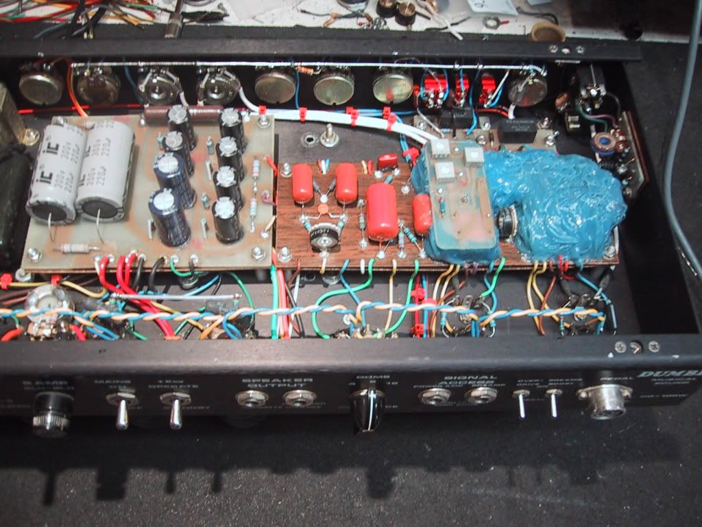
[IMG
 758]http://i205.photobucket.com/albums/bb17 ... on/195.jpg[/img]
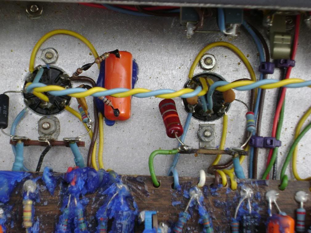