Hey guys. I'm still at it just rethinking a few things.
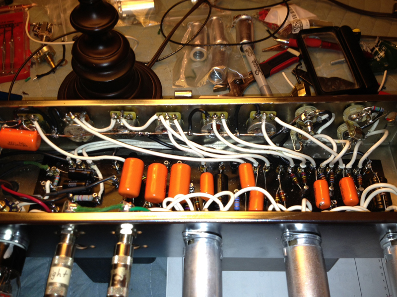
I added the bright inputs and I have new ceramic 9-pin sockets that will go in this weekend.
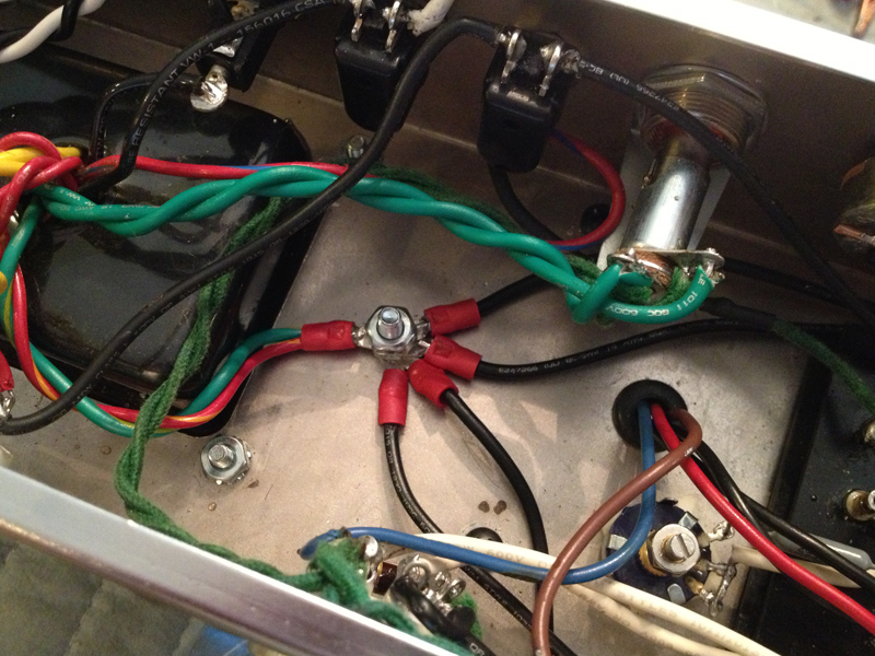
After moving the first stage ground and making progress, I moved some of the other grounds and the amp got even quieter. So, I decided to completely bail on the original grounding scheme. I took all grounds off the PT mounting posts. I added a second ground on the filter caps so the first filter stage (parallel pair) is grounded separately from the other two caps. I removed the original bus and went with a bus wire soldered to the back of the pots and terminated at the input jacks. This bus has the vol, tone, presence, gain stage grounds as well as the additional filter cap ground.
The connections on a new ground post are first filter cap stage, PT center taps, power tube cathodes and bias supply.
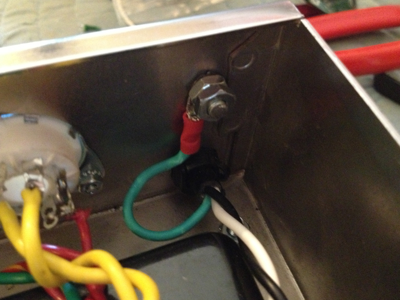
Also moved the earth lead to it's own chassis point.
[img:800:600]http://www.crenshawweb.com/bassman/build70.jpg[/img]
[img:800:600]http://www.crenshawweb.com/bassman/build71.jpg[/img]
[img:800:600]http://www.crenshawweb.com/bassman/build72.jpg[/img]
Peace,
Mark
Issue With Bassman 5F6A Build
Moderators: pompeiisneaks, Colossal
-
Reeltarded

- Posts: 10189
- Joined: Sat Feb 14, 2009 4:38 am
- Location: GA USA
Re: Issue With Bassman 5F6A Build
haha it's looking rather awesome by now. I love your attitude.
"Oh yeah? Well, see how you like this!" -solders-

"Oh yeah? Well, see how you like this!" -solders-
Signatures have a 255 character limit that I could abuse, but I am not Cecil B. DeMille.

Re: Issue With Bassman 5F6A Build
Exactly! Btw, is that solder on that v1 orange drop?
But, nice build!!!!
But, nice build!!!!
Re: Issue With Bassman 5F6A Build
What's the consensus: should he also move the screen supply to the new main ground?
Re: Issue With Bassman 5F6A Build
Technically, it should be at the powertube cathodes with the bias ground. But this is a tweed bassman, why mess up a good design with technical improvements, before you know it, someone will suggest to replace those noisy and troublesome vaccuum tubes with solid state devices and, and.... Whoa! Did I just do that? 
-
Reeltarded
- Posts: 10189
- Joined: Sat Feb 14, 2009 4:38 am
- Location: GA USA
Re: Issue With Bassman 5F6A Build
Oh God.. noooooooooo!

Signatures have a 255 character limit that I could abuse, but I am not Cecil B. DeMille.
Re: Issue With Bassman 5F6A Build
I got the new sockets installed. I'm definitely getting better at working in the chassis. These were easy compared to the last two rounds of soldering.
So, new numbers. The plates on V1 are finally balanced out! Hopefully, I'm done with tube sockets.
V1
1 146vdc
2
3 2.42vdc
6 144vdc
7
8 2.42vcd
V2
1 294vdc
2
3 2.06vdc
6 293vdc
7 248vdc
8 249vdc
V3
1 258vdc
2
3 43.3vdc
6 245vdc
7
8 43.3vdc
V4
1
3 431vdc
4 430vdc
5 -50.4vdc
6 433vdc
8
V5
1
3 434vdc
4 433vdc
5 -50.4vdc
6 435vdc
8
Re: Issue With Bassman 5F6A Build
Thanks for the observation Firestorm.Firestorm wrote:A very secondary issue at this point, but it looks like you may have your output tube heaters wired out of phase (awful hard to tell with all green wire). Pin 7 on one socket has to connect to Pin 7 on the other (and 2 goes to 2). Otherwise the 60Hz hum won't phase cancel. That might be part of the residual hum you have.Guitarnut wrote:The amp is very quiet now with about 1/4 the hum as before.
They're in phase. I was careful to make sure they were all the way down, though I don't think it matters on the 9 pin tubes. I remembered reading that in Gerald Weber article some time back.
Peace,
Mark
Re: Issue With Bassman 5F6A Build
Thanks Structo.Structo wrote:Not that this is the problem but looking at your pictures of V4 & V5, the screen resistor appears to be 47K.
Yellow, violet, orange.
Double check your shielded cable from the input jack to pin 2 on V1.
Common mistake to damage the shielded cable when soldering, shorting out the input.
Measure resistance from pin 2 to ground, should not be zero.
Must be the bad white balance of my camera. They meter at 470Ω.
No shielded wire in this build. I may go back and try it if I end up with noisy inputs.
Peace,
Mark
-
Reeltarded
- Posts: 10189
- Joined: Sat Feb 14, 2009 4:38 am
- Location: GA USA
Re: Issue With Bassman 5F6A Build
How long until you plug it in? It's driving me crazy.
Looks good!
I do all my socket dressing with the chassis standing on end.. mostly, unless I am soldering for speed on a mod I just thought of.
Looks good!
I do all my socket dressing with the chassis standing on end.. mostly, unless I am soldering for speed on a mod I just thought of.
Signatures have a 255 character limit that I could abuse, but I am not Cecil B. DeMille.
Re: Issue With Bassman 5F6A Build
After adding the Bright inputs, I went back and checked resistance as Martin suggested. I have 35K showing up on the grids that should be 0Ω. 35K just happens to be the same as the junction of the mix resistors with no plug in either jack.
Normal 1
Hot to Ground 1004K
Pin 2 to Ground 1036K
Pin 7 to Ground 35K
Normal 2
Hot to Ground 141K
Pin 2 to Ground 73K
Pin 7 to Ground 35K
Bright 1
Hot to Ground 1004K
Pin 2 to Ground 35K
Pin 7 to Ground 1036K
Bright 2
Hot to Ground 141K
Pin 2 to Ground 35K
Pin 7 to Ground 72K
Peace,
Mark
Normal 1
Hot to Ground 1004K
Pin 2 to Ground 1036K
Pin 7 to Ground 35K
Normal 2
Hot to Ground 141K
Pin 2 to Ground 73K
Pin 7 to Ground 35K
Bright 1
Hot to Ground 1004K
Pin 2 to Ground 35K
Pin 7 to Ground 1036K
Bright 2
Hot to Ground 141K
Pin 2 to Ground 35K
Pin 7 to Ground 72K
Peace,
Mark
Re: Issue With Bassman 5F6A Build
I tried...still not making any sound. Likely has something to do with the issue I posted above.Reeltarded wrote:How long until you plug it in? It's driving me crazy.
Looks good!
I'm gonna recheck the wiring on the jacks. Arrrrgh!
Peace,
Mark
-
martin manning

- Posts: 14308
- Joined: Sun Jul 06, 2008 12:43 am
- Location: 39°06' N 84°30' W
Re: Issue With Bassman 5F6A Build
34k to ground on the other grid is good (the two 68k's paralleled), my mistake. Did you try to check the idle current on the output tubes? The power tube pin 6 vs. pin 4 still looks odd.

Re: Issue With Bassman 5F6A Build
V2 has a 100V deviation and the power tube readings are out of wack, something tells me when you actually set the bias, there will be changes in the V4/V5 area.
TM
TM
Re: Issue With Bassman 5F6A Build
Well, the amp is really starting to look good!
Those input jacks can be a bit challenging for a first timer.
I assume you used switching jacks (3 lugs each).
[img:329:513]https://lh4.googleusercontent.com/-Dt-M ... Inputs.JPG[/img]
Look at this picture, this is the rear view of the jacks.
Note the little jumper between the top and middle lugs on the top jacks.
The 1M resistor goes from the top lug to the bottom lug on the top two jacks.
It's hard for me to see how your jacks are wired in the picture.
The 1004K you measured is the 1M grid leak resistor on the jack.
You do not have the required permissions to view the files attached to this post.
Tom
Don't let that smoke out!
Don't let that smoke out!